
Page 17 - Bellofram Design Manual
P. 17
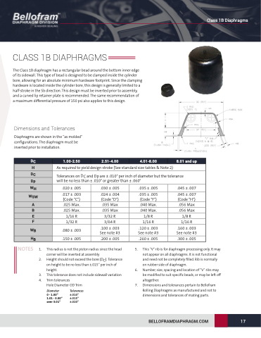
  CLASS 1B DIAPHRAGMS
The Class 1B diaphragm has a rectangular bead around the bottom inner edge of its sidewall. This type of bead is designed to be clamped inside the cylinder bore, allowing for an absolute minimum hardware footprint. Since the clamping hardware is located inside the cylinder bore, this design is generally limited to a half-stroke in the Sb direction. This design must be inverted prior to assembly, and a curved lip retainer plate is recommended. The same recommendation of
a maximum differential pressure of 150 psi also applies to this design.
Dimensions and Tolerances
Diaphragms are shown in the “as molded” configurations. The diaphragm must be inverted prior to installation.
Class 1B Diaphragms
                                                                                                              As required to yield design stroke (See standard size tables & Note 2)
Tolerances on DC and Dp are ± .010" per inch of diameter but the tolerance will be no less than ± .010" or greater than ± .060"
  .020 ± .005
.017 ± .003 (Code "C") .025 Max.
.025 Max.
1/16 R
1/32 R .150 ± .005
.030 ± .005
.024 ± .004 (Code "D") .035 Max
.035 Max
3/32 R
3/64 R .200 ± .005
.035 ± .005
.035 ± .005 (Code "F") .040 Max.
.040 Max.
1/8 R
1/16 R .260 ± .005
.045 ± .007
.045 ± .007 (Code "H") .056 Max
.056 Max
1/8 R
1/16 R .300 ± .005
        .080 ± .003
   .100 ± .003 See note #3
   .120 ± .003 See note #3
   .160 ± .003 See note #3
  NOTES 1. 2.
3. 4.
This radius is not the piston radius since the head
corner will be inverted at assembly
Height should not exceed the bore (DC). Tolerance
on height to be no less than ±.015” per inch of
height. 6. This tolerance does not include sidewall variation
DC
     1.00-2.50
2.51-4.00
4.01-8.00
8.01 and up
     H
 DC
 Dp
 WH
 WSW
 A
 B
 E
F
   WB
HB
     Trim tolerances
Hole Diameter OD Trim
5.
7.
This “V” rib is for diaphragm processing only. It may not appear on all diaphragms. It is not functional and need not be completely filled. Rib is normally on rubber side of diaphragm.
Number, size, spacing and location of “V” ribs may be modified to suit specific beads, or may be left off altogether.
Dimensions and tolerances pertain to Bellofram Rolling Diaphragms as manufactured and not to dimensions and tolerances of mating parts.
Diameter
0 - 1.00” 1.01 - 3.00” over 3.01”
Tolerances
±.010” ±.015” ±.020”
BELLOFRAMDIAPHRAGM.COM
 17
