
Page 19 - Bellofram Design Manual
P. 19
HARDWARE DESIGN
General
The Bellofram Rolling Diaphragm rolls back and forth from the piston to the cylinder wall. This unique seal employs very simple hardware design that is easy to develop and economical to fabricate.
Cylinder Bore DC
0.37-0.99 1.00-2.50
2.51-4.00
4.01-8.00
Convolution Width C
.0625
.0937
.1562
.250
Piston Skirt Length
H + SA
2
H + SA
2
H + SA
2
H + SA
2
Cap* Length
Stroke in SA Direction Stroke in SA Direction Stroke in SA Direction Stroke in SA Direction
Rp **RF
.0312 .0312 .0625 .0625 .0937 .0937 .125 .125
NOTES: *Plus diaphragm head & retainer thickness **On hardware Chart refers to Fig. 17.
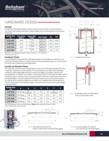
Hardware Finish
Fig. 17: Hardware Dimensions
One advantage of utilizing Bellofram Rolling Diaphragms is that hardware smoothness is not critical and, therefore, there is no need for expensive, finely machined surfaces. A surface finish of 63 microinches is sufficient for most applications.
Curved Lip Retainer Plates
The head corners of some classes of diaphragms require inversion during assembly to form the convolution. Therefore, it is quite possible, in some installations and under certain operating conditions, that the diaphragm will try to re-invert to its original “as-molded” position, thus causing sidewall “scrubbing”. This condition is illustrated in Fig. 18. To eliminate this effect, curved lip retainer plates, as shown in Fig. 20, are recommended to hold the inverted head corner of the rolling diaphragm in intimate contact with the piston head corner. The use of retainer plate in the original piston assembly is highly recommended, since it greatly reduces the possibility of incorrect reassembly of the rolling diaphragm. A recommended curved lip retainer plate design
is described below.
Cylinder Bore DC
0.37-0.99 1.00-2.50
2.51-4.00
4.01-8.00
ABCDEFG
Dp+2WSW Dp+2WSW Dp+2WSW
Dp+2WSW
Not required
.7 Dp
.7 Dp
.7 Dp
.015 1/16
.025 3/32
.030 7/64
.030 1/8
1/8 Not .025 required
Fig. 18: Diaphragm inversion resulting from lack of curved retainer plate.
NOTES: Dp=piston skirt outside diameter, WSW=Max. sidewall thickness of BRD Chart refers to Fig. 19 and Fig. 20.
Fig. 19: Flat washer type retainer for
Classes 3C and 4C (Pre-convoluted Diaphragms).
Fig. 20: Curved lip retainer for Classes 3,
4, 1A and 1B (“Top-Hat” Diaphragms).
3/16 .010
7/32 .015 .040
.030 1/4 .015 .060
BELLOFRAMDIAPHRAGM.COM 19
Hardware Design
