
Page 21 - Bellofram Design Manual
P. 21
Diaphragm Flange Retention Methods
Ring Clamp (Fig. 25) – In order to provide for fast disassembly, a “V” style clamp ring is frequently used. This type of ring can be opened quickly for disassembly by removing one toggle clamp lever. The retainer plate is provided with a “keyhole slot” and the retaining screw is provided with two wings which bear against the top surface of the retainer plate. This retainer plate is quickly removed by turning it 90o at which point the wings and the bolt drop into the keyhole slots. In general, this design is for low pressures.
Pivoted Rocking Bracket (Fig. 26) – This is another low cost design which also has the advantage of quick assembly and disassembly. A pivoted rocking bracket is attached to the housing flange. The central jam screw holds the bonnet firmly against the mating flange area. The unit can be disassembled quickly by loosening the screw and pivoting the bracket to release the bonnet assembly and rolling diaphragm. In general, this design is also limited to low pressure.
Beveled Edge Retainer Plate (Fig. 27) – By the use of a beveled edge retainer ring, flange bolts can be eliminated. A groove is provided in the extension of the cylinder housing flange and during assembly the beveled edge ring is snapped into the groove which, in turn, loads the bonnet assembly onto the mating bead. Generally, the clamping forces produced by a design of this type are fairly low, and therefore, these applications should be restricted for use with low pressure.
CLASS 1A DIAPHRAGMS
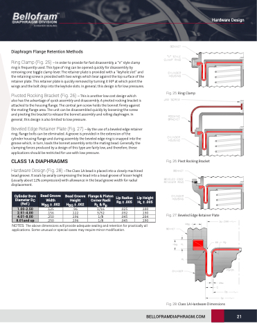
Hardware Design (Fig. 28) –The Class 1A bead is placed into a closely machined bead groove. It seals by axially compressing the bead into a bead groove of lesser height (usually about 12% compression) with allowance in the bead groove width for radial displacement.
Fig. 25: Ring Clamp
Cylinder Bore Diameter DC (Ref.)
1.00-2.50 2.51-4.00 4.01-8.00 8.01and up
Bead Groove Width WBG ± .002 .125 .156 .250 .250
Bead Groove Height HBG ± .002 .96
.122 .196 .196
Flange & Piston Corner Radii RL & Rp 1/16
3/32
1/8
1/8
Lip Radius RR ± .005
.025 .032 .045 .045
Lip Height HL ± .005
.100 .130 .204 .190
Fig. 26: Pivot Rocking Bracket
Fig. 27: Beveled Edge Retainer Plate
NOTES: The above dimensions will provide adequate sealing and retention for practically all applications. Some unusual or special cases may require minor modification.
Fig. 28: Class 1A Hardware Dimensions BELLOFRAMDIAPHRAGM.COM 21
Hardware Design
