
Page 23 - Bellofram Design Manual
P. 23
APPLICATION DATA
Designing For Diaphragm Trim & Perforation
Some rolling diaphragms require perforations through the flange or head to accommodate a fastening means either to the flange or head. This necessitates a punching operation for head holes, flange holes, or trimming the outside flange periphery, so that the rolling diaphragm will mate with the configuration of the piston, bonnet or cylinder housing.
We recommend that all perforations or flange trim be performed by us prior to shipment. Please submit sketches of required perforations or trim with quotation request, or with your order. Good design procedures for trim and perforation are as follows:
Relationship of Hole Pattern – Whenever there are holes in the head and flange, always indicate whether the hole pattern in the head and the hole pattern in the flange must be trimmed with a definite angular relationship. The manufacture of trim tools which will maintain this fixed angular orientation involves additional expense.
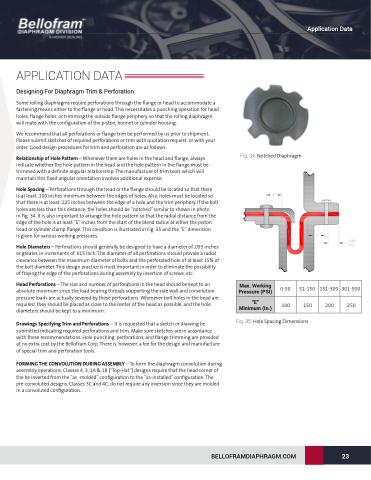
Hole Spacing – Perforations through the head or the flange should be located so that there
is at least .100 inches minimum between the edges of holes. Also, holes must be located so that there is at least .125 inches between the edge of a hole and the trim periphery. If the bolt holes are less than this distance, the holes should be “notched” similar to shown in photo
in Fig. 34. It is also important to arrange the hole pattern so that the radial distance from the edge of the hole is at least ”E” inches from the start of the blend radius at either the piston head or cylinder clamp flange. This condition is illustrated in Fig. 35 and the “E” dimension
is given for various working pressures.
Hole Diameters – Perforations should generally be designed to have a diameter of .093 inches or greater, in increments of .015 inch. The diameter of all perforations should provide a radial clearance between the maximum diameter of bolts and the perforated hole of at least 15% of the bolt diameter. This design practice is most important in order to eliminate the possibility of fraying the edge of the perforations during assembly by insertion of screws, etc.
Head Perforations – The size and number of perforations in the head should be kept to an absolute minimum since the load bearing threads supporting the side wall and convolution pressure loads are actually severed by these perforations. Whenever bolt holes in the bead are required, they should be placed as close to the center of the head as possible, and the hole diameters should be kept to a minimum.
Drawings Specifying Trim and Perforations – It is requested that a sketch or drawing be submitted indicating required perforations and trim. Make sure sketches are in accordance with these recommendations. Hole punching, perforations, and flange trimming are provided at no extra cost by the Bellofram Corp. There is, however, a fee for the design and manufacture of special trim and perforation tools.
FORMING THE CONVOLUTION DURING ASSEMBLY – To form the diaphragm convolution during assembly operations. Classes 4, 3, 1A & 1B (“Top-Hat”) designs require that the head corner of the be inverted from the “as -molded” configuration to the “as-installed” configuration. The pre-convoluted designs, Classes 3C and 4C, do not require any inversion since they are molded in a convoluted configuration.
Fig. 34: Notched Diaphragm
Max. Working Pressure (PSI)
“E” Minimum (In.)
0-50
.100
51-150 151-300 301-500
Fig. 35: Hole Spacing Dimensions
BELLOFRAMDIAPHRAGM.COM
23
.150
.200 .250
Application Data
