
Page 24 - Bellofram Design Manual
P. 24
ALTERNATE METHODS OF ATTACHING DIAPHRAGM TO PISTON – Whenever it is undesirable to attach the diaphragm to the piston head by means of rivets, screws, etc., which require a hole through the head of the diaphragm, attachment may be made by either of the following means:
1. Double Sided Pressure Sensitive Tape: Apply to one of the areas to be bonded and then press on the mating surface. Clean all surfaces to be bonded with perchloroethylene and acetone to remove all surface films. It may be necessary to abrade the surfaces prior to cleaning to obtain improved bonds. The tape should be die cut in the shape of a disc with the diameter equal to the piston head diameter allowing sufficient margin for the disc to form down over the head corner radius. To prevent pleating in the area of the head corner radius, the head disc should be die cut with frequent notches. The above procedure works well with most elastomers, however, for bonding silicone to metal piston heads, see below.
2. Liquid Cements: In using liquid cements or semi-liquid cements for bonding a diaphragm to a piston head, the cement must be restricted to the area to be bonded. The adhesive should be applied to the entire top surface of the piston including the head corner and to the mating “Fabric side” of the diaphragm. Any cement which inadvertently comes in contact with the sidewall area of the piston of the diaphragm (excluding the Head Corner Radius) must be completely removed prior to application, of the diaphragm. All surfaces must be pre-cleaned as noted previously.
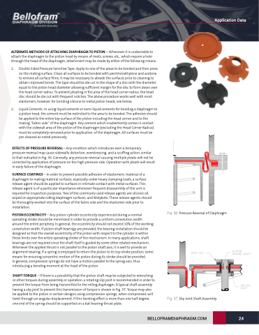
EFFECTS OF PRESSURE REVERSAL – Any condition which introduces even a temporary pressure reversal may cause sidewalls distortion, overstressing, and a scuffing action, similar to that indicated in Fig. 36. Generally, any pressure reversal causing multiple pleats will not be corrected by application of pressure on the high pressure side. Operation with pleats will result in early failure of the diaphragm.
SURFACE COATINGS – In order to prevent possible adhesion of elastomeric material of a diaphragm to mating material surfaces, especially under heavy clamping loads, a surface release agent should be applied to surfaces in intimate contact with metal surfaces. This release agent is of a particular importance whenever frequent disassembly of the unit is required for inspection purposes. Two of the commonly used release agents are silicone oil, wiped on appropriate rolling diaphragm surfaces, and Molykote. These release agents should be thoroughly worked into the surface of the fabric side and the elastomer side prior to installation.
PISTON ECCENTRICITY – Any piston-cylinder eccentricity experienced during a normal operating stroke should be minimized in order to provide a uniform convolution width around the entire periphery. In general, the eccentricity should not exceed 10% of the working convolution width. If piston shaft bearings are provided, the bearing installation should be designed so that the overall eccentricity of the piston with respect to the cylinder is within these limits over the entire operating stroke of the mechanism. In many applications, shaft bearings are not required since the shaft itself is guided by some other related mechanism. Whenever the applied thrust is not parallel to the piston shaft axis, it is well to provide an alignment bearing. If a spring is employed to return the piston to its top stroke position, some means for ensuring concentric motion of the piston during its stroke should be provided.
In general, compression springs do not have a motion parallel to the spring axis, thus introducing a bending moment at the head of the piston.
SHAFT TORQUE – If there is a possibility that the piston shaft may be subjected to wrenching or other torques during assembly or operation, a rotating slip joint is recommended in order to prevent the torque from being transmitted to the rolling diaphragm. A typical shaft assembly having a slip joint to prevent this transmission of torque is shown in Fig. 37. Torque may also be applied to the piston in certain designs using compression springs, when compressed, will twist through an angular displacement. If this twisting effect is more than one half degree, one end of the spring should be supported on a ball bearing thrust plate.
Fig. 36: Pressure Reversal of Diaphragm
Fig. 37: Slip Joint Shaft Assembly
BELLOFRAMDIAPHRAGM.COM 24
Application Data
