
Page 22 - Bellofram Design Manual
P. 22
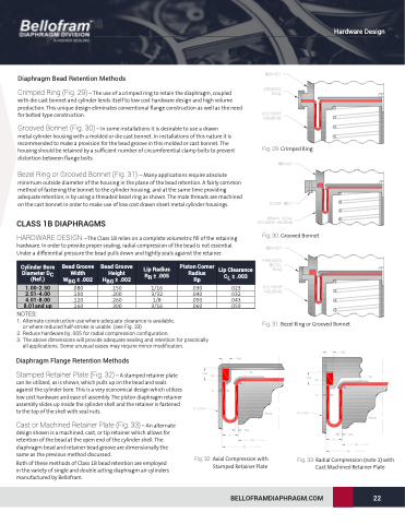
 Diaphragm Bead Retention Methods
Crimped Ring (Fig. 29) – The use of a crimped ring to retain the diaphragm, coupled with die cast bonnet and cylinder lends itself to low cost hardware design and high volume production. This unique design eliminates conventional flange construction as well as the need for bolted type construction.
Grooved Bonnet (Fig. 30) – In some installations it is desirable to use a drawn
metal cylinder housing with a molded or die cast bonnet. In installations of this nature it is recommended to make a provision for the bead groove in this molded or cast bonnet. The housing should be retained by a sufficient number of circumferential clamp bolts to prevent distortion between flange bolts.
Bezel Ring or Grooved Bonnet (Fig. 31) – Many applications require absolute minimum outside diameter of the housing in the plane of the bead retention. A fairly common method of fastening the bonnet to the cylinder housing, and at the same time providing adequate retention, is by using a threaded bezel ring as shown. The male threads are machined on the cast bonnet in order to make use of low cost drawn sheet metal cylinder housings.
CLASS 1B DIAPHRAGMS
HARDWARE DESIGN –The Class 1B relies on a complete volumetric fill of the retaining hardware. In order to provide proper sealing, radial compression of the bead is not essential. Under a differential pressure the bead pulls down and tightly seals against the retainer.
Fig. 29: Crimped Ring
Cylinder Bore Diameter DC (Ref.)
1.00-2.50 2.51-4.00 4.01-8.00 8.01and up
Bead Groove Width WBG ± .002 .080 .100 .120 .160
Bead Groove Height HBG ± .002 .150 .200 .260 .300
Lip Radius RR ± .005
1/16 3/32 1/8 3/16
Piston Corner Radius
Rp
.030
.040
.050
.060
Lip Clearance CL ± .003
.023 .032 .043 .059
NOTES:
1. Alternate construction use where adequate clearance is available,
Fig. 31: Bezel Ring or Grooved Bonnet
or where reduced half-stroke is usable. (see Fig. 33)
2. Reduce hardware by .005 for radial compression configuration.
3. The above dimensions will provide adequate sealing and retention for practically
all applications. Some unusual cases may require minor modification.
Diaphragm Flange Retention Methods
Stamped Retainer Plate (Fig. 32) – A stamped retainer plate can be utilized, as is shown, which pulls up on the bead and seals against the cylinder bore. This is a very economical design which utilizes low cost hardware and ease of assembly. The piston diaphragm retainer assembly slides up inside the cylinder shell and the retainer is fastened to the top of the shell with seal nuts.
Cast or Machined Retainer Plate (Fig. 33) – An alternate design shown is a machined, cast, or tip retainer which allows for retention of the bead at the open end of the cylinder shell. The diaphragm bead and retainer bead groove are dimensionally the same as the previous method discussed.
Both of these methods of Class 1B bead retention are employed in the variety of single and double acting diaphragm air cylinders manufactured by Bellofram.
Fig. 32: Axial Compression with Stamped Retainer Plate
Fig. 33: Radial Compression (note 1) with Cast Machined Retainer Plate
Fig. 30: Grooved Bonnet
BELLOFRAMDIAPHRAGM.COM 22
Hardware Design
