
Page 20 - Bellofram Design Manual
P. 20
CLASS 4 & 4C DIAPHRAGMS Diaphragm Flange Retention Methods
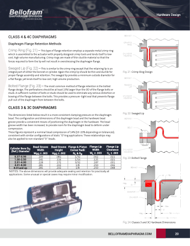
Crimp Ring (Fig. 21) – This type of flange retention employs a separate metal crimp ring which is assembled to the actuator with properly designed crimp tools and lends itself to low cost, high volume manufacturing. Crimp rings are made of thin ductile material so that the forces required to form the lip will not result in overstressing the diaphragm flange.
Swaged Lip (Fig. 22) – This is similar to the crimp ring except that the retaining lip is an integral part of either the bonnet or cylinder. Again the crimp lip should be thin and ductile for proper flange assembly and retention. The swaged lip provides a minimum outside diameter for a flat flange, yet lends itself to low cost, high volume production.
Bolted Flange (Fig. 23) – The most common method of flange retention is the bolted flange design. The perforations should be at least 15% larger than the OD of the flange bolts or studs. A sufficient number of bolts or studs should be used to eliminate any serious distortion or bowing of the flange between the bolts. This provides a pressure- tight seal that prevents flange pull-out of the diaphragm from between the bolts.
CLASS 3 & 3C DIAPHRAGMS
The dimensions listed below result in a more consistent clamping pressure on the diaphragm bead. The configuration and dimensions of the diaphragm bead and the hardware bead groove provide a convenient means of positioning the diaphragm in the hardware. The bead groove width has been increased, to provide room for the diaphragm bead to deform under compression.
These figures represent a nominal bead compression of 14% (10–20% depending on tolerances), consistent with similar configurations of static ”O”ring applications. These relationships may also be applied to non-standard “D” beads.
Fig. 21: Crimp-Ring Design
Cylinder Bore DC (Ref.) Diameter
0.37-0.99 1.00-2.50 2.51-4.00 4.01-8.00 8.01and up
Bead Groove Width WBG ± .003 .109 .141 .228 .281 .281
Bead Groove Height HBG ± .002 .081 .116 .172 .232 .232
Flange & Piston Corner Radii RL & Rp 1/32
1/16
3/32
1/8
1/8
Flange Lip Width WL ± .003 .062 .125 .187 .250 .250
Flange Lip Clearance CL ± .003 .021 .021 .031 .036 .048
Fig. 23: Bolted Flange
NOTES: The above dimensions will provide adequate sealing and retention for practically all applications. Some unusual or special cases may require minor modification.
Fig. 22: Swaged Lip
Fig. 24: Classes 3 and 3C Hardware Dimensions BELLOFRAMDIAPHRAGM.COM 20
Hardware Design
