
Page 9 - JOJAPS_VOL13
P. 9
Ir Hairanus Tarigan / JOJAPS – JOURNAL ONLINE JARINGAN PENGAJIAN SENI BINA
1.2 Formulation of the Problem
This study tried to design a Kincir Generator 50 KVA 380/220 V protection device from short circuit current or over
current. This protection device is able to secure the generator from damage due to a short circuit between the phase wire and
neutral wire or when the generator has excessive load. This built-in protection device is designed or equipped with protective
aids, namely: three current transformers, over current relays, three phase magnetic breaker, two pilot lights, connecting cables,
panel box and supporting pole panel box. The panel box is needed as a box where the protective aids are installed. Each phase
current coming out of the three generator terminals is passed through the three primary coil current transformers, the
transformer secondary terminal of each current is connected to the over current relay coil terminal which is adjusted according
to the phase sequence, then a closed circuit is made where the AC 220 V source from the generator downstream of the
magnetic breaker is connected to the over current relay contact which is NC (Normally Close) and to the magnetic breaker coil
terminal.
1.3 Scope of the Problem
This research is only focused on the manufacture of a 50 kva 380/220 v waterwheel generator protection device from short
circuit and over current interference. Current transformer ratings are limited to 75/5 A, maximum over current relay input of 5
A, magnetic breaker capacity is limited to no more than 100 A, panel box size is 60 x 40 x 20 cm, height of panel box support
is 1.5 m, panel box equipped with 2 pilot lights to determine the status of the protection device whether it is ON or OFF.
1.4 Research Purposes
The research oectives are:
1. To make a short-circuit current or over current protection device for the waterwheel generator in village Desa Suka Dame
2. To get a protective device that has the ability reliable in interrupted short circuit current or over current so that the
generator is kept safe
3. To be an analytical study and comparative study for Engineering students Energy Conversion Department of
Mechanical Engineering, Medan State Polytechnic at Laboratorium Energy Conversion Technique.
2.0 Theoretical Basis
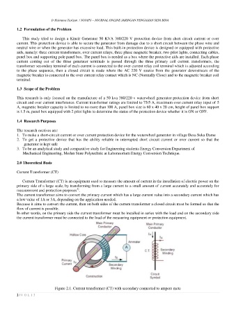
Current Transformer (CT)
Current Transformer (CT) is an equipment used to measure the amount of current in the installation of electric power on the
primary side of a large scale, by transforming from a large current to a small amount of current accurately and accurately for
3)
measurement and protection purposes .
The current transformer aims to convert the primary current which has a large current value into a secondary current which has
a low value of 1A or 5A, depending on the application needed.
Because it aims to convert the current, then on both sides of the current transformer a closed circuit must be formed so that the
flow of current is possible.
In other words, on the primary side the current transformer must be installed in series with the load and on the secondary side
the current transformer must be connected to the load of the measuring equipment or protection equipment.
Figure 2.1. Current transformer (CT) with secondary connected to ampere mete
2 | V O L 1 3