
Page 184 - Physics Coursebook 2015 (A level)
P. 184
Cambridge International AS Level Physics
172
Y
Potential dividers
How can we get an output of 3.0 V from a battery of e.m.f. 6.0 V? Sometimes we want to use only part of the e.m.f.
of a supply. To do this, we use an arrangement of resistors called a potential divider circuit.
Figure 12.6 shows two potential divider circuits, each connected across a battery of e.m.f. 6.0 V and of negligible
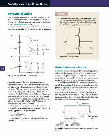
QUESTION
7 Determine the range of Vout for the circuit in Figure 12.7 as the variable resistor R2 is adjusted over its full range from 0 Ω to 40 Ω. (Assume the supply of e.m.f. 10 V has negligible internal resistance.)
a 10Ω
R1= 200 Ω R2 V
10V
R2 Figure 12.7 For Question 7.
Potentiometer circuits
A potentiometer is a device used for comparing potential differences. For example, it can be used to measure the e.m.f. of a cell, provided you already have a source whose e.m.f. is known accurately. As we will see, a potentiometer can be thought of as a type of potential divider circuit.
A potentiometer consists of a piece of resistance wire, usually 1 m in length, stretched horizontally between two points. In Figure 12.8, the ends of the wire are labelled A and B. A driver cell is connected across the length of wire. Suppose this cell has an e.m.f. Eo of 2.0 V. We can then
say that point A is at a voltage of 2.0 V, B is at 0 V, and the midpoint of the wire is at 1.0 V. In other words, the voltage decreases steadily along the length of the wire.
E
Vin = 6.0 V b
R1 Vin = 6.0 V R2
Vout = 3.0 V
Vout
internal resistance. The high-resistance voltmeter measures the voltage across the resistor of resistance R .
We refer to this voltage as the output voltage, V , of out
the circuit. The first circuit, a, consists of two resistors
of values R1 and R2. The voltage across the resistor of resistance R2 is half of the 6.0 V of the battery. The second potential divider, b, is more useful. It consists of a single variable resistor. By moving the sliding contact, we can achieve any value of Vout between 0.0 V (slider at the bottom) and 6.0 V (slider at the top).
The output voltage Vout depends on the relative values of R1 and R2. You can calculate the value of Vout using the following potential divider equation:
Vout = ( R2 )×Vin R1 +R2
In this equation, Vin is the total voltage across the two resistors.
o driver cell AB
=200Ω
V Vout Figure 12.6 Two potential divider circuits.
2
cell X (unknown e.m.f.)
EX
sensitive
jockey galvanometer
potentiometer wire
Figure 12.8 A potentiometer connected to measure the e.m.f. of cell X.
