
Page 185 - Physics Coursebook 2015 (A level)
P. 185
Chapter 12: Practical circuits
Now, suppose we wish to measure the e.m.f. EX
of cell X (this must have a value less than that of the driver cell). The positive terminal of cell X is connected
to point A. (Note that both cells have their positive terminals connected to A.) A lead from the negative terminal is connected to a sensitive galvanometer (e.g. a microammeter), and a lead from the other terminal of the galvanometer ends with a metal jockey. This is a simple connecting device with a very sharp edge that allows very precise positioning on the wire.
If the jockey is touched onto the wire close to point A, the galvanometer needle will deflect in one direction. If the jockey is touched close to B, the galvanometer needle will deflect in the opposite direction. Clearly there must be some point Y along the wire which, when touched by the jockey, gives zero deflection – the needle moves neither to the left nor the right.
In finding this position, the jockey must be touched gently and briefly onto the wire; the deflection of the galvanometer shows whether the jockey is too far to the left or right. It is important not to slide the jockey along the potentiometer wire as this may scrape its surface, making it non-uniform so that the voltage does not vary uniformly along its length.
When the jockey is positioned at Y, the galvanometer gives zero deflection, showing that there is no current through it. This can only happen if the potential difference across the length of wire AY is equal to the e.m.f. of cell
X. We can say that the potentiometer is balanced. If the balance point was exactly half-way along the wire, we would be able to say that the e.m.f. of X was half that of the driver cell.
To calculate the unknown e.m.f. EX we measure the length AY. Then we have:
EX = AY × Eo AB
where Eo is the e.m.f. of the driver cell.
The potentiometer can be thought of as a potential
divider because the point of contact Y divides the resistance wire into two parts, equivalent to the two resistors of a potential divider.
Comparing e.m.f.s with a potentiometer
When a potentiometer is balanced, no current flows from the cell being investigated. This means that its terminal p.d. is equal to its e.m.f.; we do not have to worry about any ‘lost volts’. This is a great advantage that a potentiometer has over a voltmeter, which must draw a small current in order to work.
However, there is a problem: the driver cell is supplying current to the potentiometer, and so the p.d. between
A and B will be less than the e.m.f. of the driver cell
(some volts are lost because of its internal resistance).
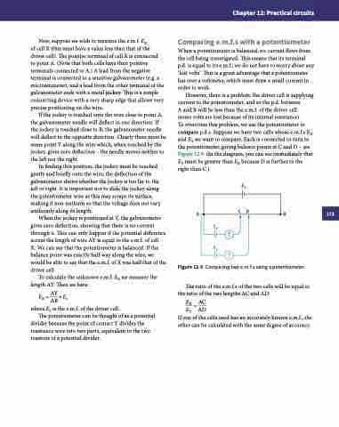
To overcome this problem, we use the potentiometer to compare p.d.s. Suppose we have two cells whose e.m.f.s EX and EY we want to compare. Each is connected in turn to the potentiometer, giving balance points at C and D – see Figure 12.9. (In the diagram, you can see immediately that EY must be greater than EX because D is further to the right than C.)
Eo AB
EX
EY
Figure 12.9 Comparing two e.m.f.s using a potentiometer.
The ratio of the e.m.f.s of the two cells will be equal to the ratio of the two lengths AC and AD:
EX = AC
EY AD
If one of the cells used has an accurately known e.m.f., the other can be calculated with the same degree of accuracy.
CD
173
