
Page 395 - Physics Coursebook 2015 (A level)
P. 395
Chapter 24: Capacitance
9 Calculate the different capacitances that can be made from three 100 μF capacitors. For each value,
draw the network that is used. [4]
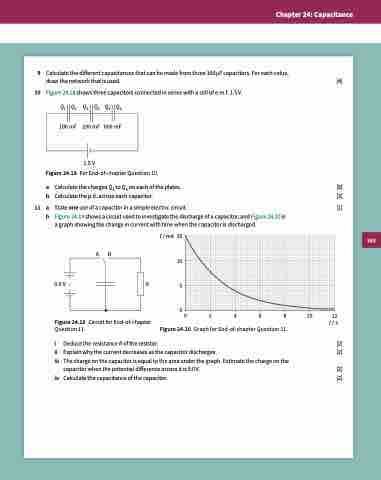
10 Figure 24.18 shows three capacitors connected in series with a cell of e.m.f. 1.5 V. Q1 Q2 Q3 Q4 Q5 Q6
1.5 V
Figure 24.18 For End-of-chapter Question 10.
a Calculate the charges Q1 to Q6 on each of the plates. [5]
b Calculate the p.d. across each capacitor. [3]
11 a
b Figure 24.19 shows a circuit used to investigate the discharge of a capacitor, and Figure 24.20 is
100 mF 200 mF 600 mF
State one use of a capacitor in a simple electric circuit. [1] a graph showing the change in current with time when the capacitor is discharged.
AB
9.0 V R
Figure 24.19 Circuit for End-of-chapter Question 11.
I / mA 15 10 5
00 2 4 6 8 10 12
Figure 24.20 Graph for End-of-chapter Question 11.
t / s [2]
[2]
[2] [2]
i Deduce the resistance R of the resistor.
ii Explain why the current decreases as the capacitor discharges.
iii Thechargeonthecapacitorisequaltotheareaunderthegraph.Estimatethechargeonthe
capacitor when the potential difference across it is 9.0 V.
iv Calculatethecapacitanceofthecapacitor.
383
