
Page 400 - Physics Coursebook 2015 (A level)
P. 400
Cambridge International A Level Physics
388
WORKED EXAMPLE
from one form to another. There is more about piezo- electric transducers in Chapter 32, where their use in ultrasound scanning is described.
For use in a microphone, the piezo-electric crystal is made into a thin sheet with metal connections on opposite sides. When a sound wave hits one side of the sheet,
the compressions and rarefactions cause the pressure
to increase and decrease. The crystal changes shape in response to these pressure changes and a small voltage
is created across the connections. Figure 25.3 shows the symbol for a microphone.
Figure 25.3 The symbol for a microphone.
Acoustic guitars and other instruments often use a piezo-electric transducer to produce an electrical output. The microphone is stuck to the body of the guitar and the electrical output can be amplified and played back through loudspeakers.
The light-dependent resistor (LDR)
A light-dependent resistor (LDR) is made of a high- resistance semiconductor. If light falling on the LDR
is of high enough frequency, photons are absorbed by the semiconductor. As some photons are absorbed, electrons are released from atoms in the semiconductor. The resulting free electrons conduct electricity and the resistance of the semiconductor is reduced.
The graph in Figure 25.4 shows the variation of the resistance of a typical LDR with light intensity. Only a narrow range of light intensity, measured in lux, is shown. A typical LDR will have a resistance of a few hundred ohms in sunlight, but in the dark its resistance will be millions of ohms.
100 80 60 40 20
0 0 10 20 30 40 50 60 70 Light intensity / lux
Figure 25.4 Resistance plotted against light intensity for an LDR.
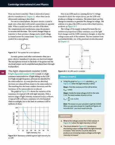
How is an LDR used as a sensing device? A voltage
is needed to drive the output device, yet the LDR only produces a change in resistance. The sensor must use this change in resistance to generate the change in voltage. The solution is to place the LDR in series with a fixed resistor, as shown in Figure 25.5.
The voltage of the supply is shared between the two resistors in proportion to their resistance, so as the light level changes and the LDR’s resistance changes, so does the voltage across each of the resistors. The two resistors form a potential divider, one of the practical circuits discussed in Chapter 12.
10 V
3.0 kΩ
Vout
Figure 25.5 An LDR used in a sensor.
1 Using the graph in Figure 25.4, calculate Vout in Figure 25.5 when the light intensity is 60 lux.
Step 1 Find the resistance of the LDR at 60 lux. RLDR = 20 kΩ
Step 2 Divide the total voltage of 10 V in the ratio 3 : 20. The total number of parts is 23 so:
20
Vout = 23 ×10=8.70V
Hint: The answer on your calculator might be 8.69565. When you give your answer to 3 significant figures, do not write 8.69 – you must round correctly.
QUESTIONS
1 What is the voltage across the 3.0 kΩ resistor in Figure 25.5 when the light intensity is 10 lux?
2 The circuit shown in Figure 25.5 produces a decreasing output voltage when the light intensity increases. How can the circuit be altered to produce an increasing output voltage as the light intensity increases?
Resistance / kΩ
