
Page 401 - Physics Coursebook 2015 (A level)
P. 401
Chapter 25: Electronics
The thermistor
The thermistors that we deal with are known as negative temperature coefficient thermistors. This means that when the temperature rises, the resistance of the thermistor
falls. This happens because the thermistor is made from a semiconductor material. One property of a semiconductor is that when the temperature rises the number of free electrons increases, and thus the resistance falls.
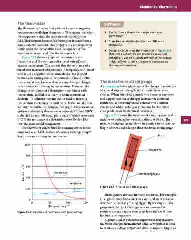
Figure 25.6 shows a graph of the resistance of a thermistor and the resistance of a metal wire plotted against temperature. You can see that the resistance of a metal wire increases with increase in temperature. A metal wire is not a negative temperature device, but it could
be used as a sensing device. A thermistor is more useful than a metal wire because there is a much larger change
in resistance with change in temperature. However, the change in resistance of a thermistor is not linear with temperature; indeed, it is likely to be an exponential decrease. This means that any device used to measure temperature electronically must be calibrated to take into account the resistance–temperature graph. The scale on an ordinary laboratory thermometer between 0 °C and 100 °C is divided up into 100 equal parts, each of which represents 1 °C. If the resistance of a thermistor were divided like this, the scale would be incorrect.
The thermistor can be used as a sensing device in the same way as an LDR. Instead of sensing a change in light level, it senses a change in temperature.
1000
800
600
400
200
00 50 100 150 Temperature / °C
Figure 25.6 Variation of resistance with temperature.
QUESTIONS
3 Explain how a thermistor can be used as a transducer.
4 State two similarities between an LDR and a thermistor.
5 Design a circuit using the thermistor in Figure 25.6 that uses a cell of 10 V and produces an output voltage of 5 V at 50 °C. Explain whether the voltage output of your circuit increases or decreases as the temperature rises.
The metal-wire strain gauge
A strain gauge takes advantage of the change in resistance of a metal wire as its length and cross-sectional area change. When stretched, a metal wire becomes narrower and longer; both these changes increase the electrical resistance. When compressed, a metal wire becomes shorter and wider; as long as it does not buckle, these changes decrease its electrical resistance.
Figure 25.7 shows the structure of a strain gauge. A thin metal wire is placed between thin sheets of plastic. The metal wire zigzags up and down its plastic base so that the length of wire used is longer than the actual strain gauge.
plastic metal wire
connecting leads Figure 25.7 A metal-wire strain gauge.
Strain gauges are used in many situations. For example, an engineer may find a crack in a wall and want to know whether the crack is growing bigger. By sticking a strain gauge over the crack the engineer can measure the resistance many days or even years later and see if there has been any movement.
A gauge used in a dynamic experiment may measure the stress changes in an aircraft wing. A processor is used to produce a voltage output and show changes in length as
thermistor
metal wire
389
Resistance / Ω
