
Page 403 - Physics Coursebook 2015 (A level)
P. 403
Chapter 25: Electronics
BOX 25.1: Potential dividers in use
Potential divider circuits are often used in electronic circuits. They are useful when a sensor is connected to a processing circuit. Suitable sensors include thermistors and light-dependent resistors (Figure 25.9). These can be used as sensors because:
■■ the resistance of a negative temperature coefficient (NTC) thermistor decreases as its temperature increases
■■ the resistance of a light-dependent resistor (LDR) decreases as the incident intensity of light increases.
a
1.5 V R1
R2 Vout
b
1.5 V
Vout
R1
ab thermistor
light-dependent resistor
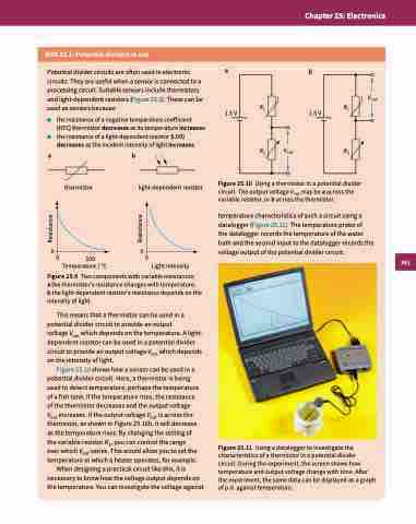
R2 Figure 25.10 Using a thermistor in a potential divider
00 100 00 Temperature / °C
Light intensity
temperature characteristics of such a circuit using a datalogger (Figure 25.11). The temperature probe of
the datalogger records the temperature of the water bath and the second input to the datalogger records the voltage output of the potential divider circuit.
Figure 25.11 Using a datalogger to investigate the characteristics of a thermistor in a potential divider circuit. During the experiment, the screen shows how temperature and output voltage change with time. After the experiment, the same data can be displayed as a graph of p.d. against temperature.
circuit. The output voltage Vout may be a across the variable resistor, or b across the thermistor.
Figure 25.9 Two components with variable resistances:
a the thermistor’s resistance changes with temperature;
b the light-dependent resistor’s resistance depends on the intensity of light.
This means that a thermistor can be used in a potential divider circuit to provide an output
voltage Vout which depends on the temperature. A light- dependent resistor can be used in a potential divider circuit to provide an output voltage Vout which depends on the intensity of light.
Figure 25.10 shows how a sensor can be used in a potential divider circuit. Here, a thermistor is being used to detect temperature, perhaps the temperature of a fish tank. If the temperature rises, the resistance of the thermistor decreases and the output voltage Vout increases. If the output voltage Vout is across the thermistor, as shown in Figure 25.10b, it will decrease as the temperature rises. By changing the setting of the variable resistor R2, you can control the range over which Vout varies. This would allow you to set the temperature at which a heater operates, for example.
When designing a practical circuit like this, it is necessary to know how the voltage output depends on the temperature. You can investigate the voltage against
391
Resistance
Resistance
