
Page 404 - Physics Coursebook 2015 (A level)
P. 404
392
Cambridge International A Level Physics
BOX 25.1: Potential dividers in use (continued)
The temperature can be raised rapidly by pouring amounts of water into the water bath. The datalogger then records both temperature and voltage and
the computer gives a display of the voltage against temperature. Dataloggers are very good at processing the collected data.
Potential divider circuits are especially useful in circuits with very small currents but where voltages are
QUESTIONS
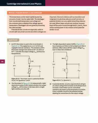
7 An NTC thermistor is used in the circuit shown in Figure 25.12. The supply has an e.m.f. of 10 V and negligible internal resistance. The resistance of the thermistor changes from 20 kΩ at 20 °C to 100 Ω at 60 °C. Calculate the output voltage Vout at these two temperatures.
1 kΩ
10 V
Vout Figure 25.12 Thermistor used in a potential divider
circuit. For Questions 7 and 8.
8 The thermistor in Figure 25.12 is replaced with a light- dependent resistor (LDR). Explain whether the output voltage Vout will increase or decrease when a bright light is shone on to the LDR.
important. Electronic devices such as transistors and integrated circuits draw only very small currents, so potential dividers are very useful where these devices are used. Where large currents are involved, because there will be some current through both R1 and R2, there will be wasted power in the resistors of the potential divider circuit.
9 The light-dependent resistor (LDR) in Figure 25.13 has a resistance of 300 Ω in full sunlight and 1 MΩ in darkness. What values will the output voltage Vout have in these two conditions?
300 Ω 12 V
Figure 25.13 For Question 9.
Vout
10 A potential divider circuit is required which will give an output voltage that increases as the temperature increases. A thermistor is to be used whose resistance decreases as the temperature increases. Draw a suitable circuit for the potential divider, showing the connections for the output voltage.
