
Page 405 - Physics Coursebook 2015 (A level)
P. 405
Chapter 25: Electronics
The operational amplifier (op-amp)
Operational amplifiers (op-amps) are among the most widely used electronic devices today, being used in a vast array of consumer, industrial and scientific devices. The amplifier is the basic building block of many electronic systems. The electrical output from the musicians in the concert shown in Figure 25.14 must be amplified before it can be passed to the loudspeakers and turned into sound.
An amplifier produces an output with more power and usually more voltage than the input. A perfect amplifier should produce an exact copy of the input. In particular, the different frequencies produced by the musicians and their instruments must be amplified by the same amount. If, for example, high-frequency notes are made louder than low-frequency notes then the whole performance will be altered. You may have noticed that people sound different when talking on the telephone. This is often because some frequencies are not amplified as much as others.
Figure 25.14 A concert – the loud music has been greatly amplified.
The goal of producing an amplifier with a constant amplification or gain might seem simple, but it is hard to achieve. Unfortunately, electronic components, such as capacitors and transistors, amplify signals of different frequencies by different amounts.
One approach is to use an amplifier with a very high gain and then provide an external circuit which reduces the gain but ensures that the overall gain is the same for signals of a greater range of frequencies. Such a device is the operational amplifier (op-amp).
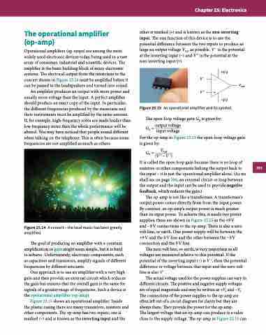
Figure 25.15 shows an operational amplifier. Inside the plastic casing there are many transistors, resistors and other components. The op-amp has two inputs; one is marked (−) and is known as the inverting input and the
other is marked (+) and is known as the non-inverting input. The one function of this device is to use the potential difference between the two inputs to produce as large an output voltage Vout as possible. V − is the potential at the inverting input (−) and V + is the potential at the non-inverting input (+).
+9 V V– –
Vout
For the op-amp in Figure 25.15 the open-loop voltage gain is given by:
G= Vout
0 (V+−V−)
It is called the open-loop gain because there is no loop of resistors or other components linking the output back to the input – it is just the operational amplifier alone. (As we shall see on page 396, an external circuit or loop between the output and the input can be used to provide negative feedback, which reduces the gain.)
The op-amp is not like a transformer. A transformer’s output power comes directly from from the input power. By contrast, an op-amp’s output power is much greater than its input power. To achieve this, it needs two power supplies; these are shown in Figure 25.15 as the +9 V
and −9 V connections to the op-amp. There is also a zero volt line, or earth. One power supply will be between the +9V and the 0V line and the other between the −9V connection and the 0 V line.
The zero volt line, or earth, is very important as all voltages are measured relative to this potential. If the potential of the inverting input (−) is V −, then the potential difference or voltage between that input and the zero volt line is also V −.
The actual voltage used for the power supplies can vary in different circuits. The positive and negative supply voltages are of equal magnitude and may be written as +Vs and −Vs. The connections of the power supplies to the op-amp are often left out of a circuit diagram for clarity but they are always there. They provide the power for the op-amp.
The largest voltage that an op-amp can produce is a value close to the supply voltage. The op-amp in Figure 25.15 can
V+
Figure 25.15 An operational amplifier and its symbol.
The open-loop voltage gain G0 is given by: G0 = output voltage
input voltage
+
–9 V
393
