
Page 407 - Physics Coursebook 2015 (A level)
P. 407
Chapter 25: Electronics
A comparator circuit can be used to compare two temperatures or two light levels. The circuit shown
in Figure 25.17 is used to give a warning when the temperature sensed by thermistor T becomes smaller than a certain value.
To understand the action of this circuit, you should notice that the positive power supply to the op-amp is also used to supply voltage and current to the thermistor T and a 10 kΩ resistor connected as a potential divider. There is also another potential divider circuit connected to the inverting input (−) of the op-amp. (Note that there is no connection where the two connecting wires are shown crossing.)
Worked example 3 explains how this circuit operates.
QUESTIONS
11 With an open-loop voltage gain G0 = 105 and power supply voltages of +9 V and −9 V, what is the smallest difference between V + and V − for which the op-amp is not saturated?
12 What happens in the circuit shown in Figure 25.17 if the supply voltages are changed to +15 V and −15 V? Is the temperature at which it switches over the same? Are the output voltages the same?
13 How can the circuit of Figure 25.17 be altered
so that the output switches from −9 V when the temperature is hot to +9 V when the temperature is cold?
14 Calculate values of V +, V − and Vout in Figure 25.17 when the resistance of T is 3 kΩ.
+9 V
–9 V Vout
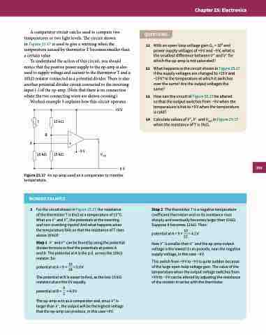
Figure 25.17 An op-amp used as a comparator to monitor
temperature.
WORKED EXAMPLE
3 For the circuit shown in Figure 25.17, the resistance of the thermistor T is 8 kΩ at a temperature of 15 °C. What are V − and V +, the potentials at the inverting and non-inverting inputs? And what happens when the temperature falls so that the resistance of T rises above 10 kΩ?
Step1 V−andV+canbefoundbyusingthepotential divider formula to find the potentials at points A
and B. The potential at A is the p.d. across the 10 kΩ resistor. So:
potential at A = 9 × 10 = 5.0 V 18
The potential at B is easier to find, as the two 15 kΩ resistors share the 9 V equally.
p o t e n t i a l a t B = 92 = 4 . 5 V
The op-amp acts as a comparator and, since V + is larger than V −, the output will be the highest voltage that the op-amp can produce, in this case +9 V.
T
B
10 kΩ
A+ 15 kΩ
15 kΩ
–
0V
Step 2 The thermistor T is a negative temperature coefficient thermistor and so its resistance rises sharply and eventually becomes larger than 10 kΩ. Suppose it becomes 12 kΩ. Then:
potentialatA=9× 10=4.1V 22
NowV+issmallerthanV−andtheop-ampoutput voltage is the lowest it can provide, near the negative supply voltage, in this case −9 V.
This switch from +9 V to −9 V is quite sudden because of the large open-loop voltage gain. The value of the temperature when the output voltage switches from +9 V to −9 V can be altered by adjusting the resistance of the resistor in series with the thermistor.
395
