
Page 409 - Physics Coursebook 2015 (A level)
P. 409
Chapter 25: Electronics
To summarise, the benefits of using negative feedback to reduce the gain of an op-amp are:
■■ less distortion
■■ increased bandwidth
■■ the gain is more stable and not affected by changes in
temperature, etc.
■■ the output resistance (impedance) can be low and the input
resistance (impedance) high.
The inverting amplifier
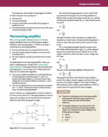
The inverting amplifier shown in Figure 25.20 uses negative feedback, but not all of the output voltage is fed back to the inverting input (−). When an op-amp is connected as an inverting amplifier:
■■ the non-inverting input (+) is connected to the 0 V line
■■ part of the output voltage (or signal) is connected to the
inverting input (−)
■■ the input voltage (or signal) is connected to the inverting
input.
To understand how the inverting amplifier works, you need to understand the concept of the virtual earth approximation. In this approximation the potential at the inverting input (−) is very close to 0 V. Why is this true? There are two steps in the argument:
■■ The op-amp multiplies the difference in potential between the inverting and non-inverting inputs, V − and V +, to produce the output voltage Vout . Because the open-loop voltage gain is very high, the difference between V − and V + must be almost zero.
The virtual earth approximation can be used to find
an expression for the gain of an inverting amplifier, as follows. If the current in the input resistor Rin is Iin and the current in the feedback resistor Rf is If , then, because point P is at 0 V:
■■ The non-inverting input (+) is connected to the zero volt line soV+ =0.ThusV− mustbeclosetozeroandtheinverting input (−) is almost at earth potential.
Point P is known as a virtual earth. It cannot actually be 0V but it is very close to 0V. This approximation is true as long as the op-amp is not saturated, and for frequencies where the open-loop voltage gain is high.
If = Vout Rf
The input resistance of the op-amp is very high and so virtually no current enters or leaves the inverting input (−) of the op-amp. This means that Iin and If must be equal
in size.
If Vin is a positive potential, then the current in the two resistors flows from left to right. Vout will be negative because the current flows from P, which is at 0 V, to the output connection, which must have a lower voltage than 0 V. Thus:
If = −Iin and
Vout = − Vin Rf Rin
The gain of the inverting amplifier is thus given by:
G = Vout = − Rf Vin Rin
The negative sign shows that when the input voltage is positive the output voltage is negative and when the input is positive the output is negative. If the input voltage is alternating then there will be a phase difference of 180° or π rad between the input and the output voltages.
QUESTIONS
Iin = Vin
Rin and
Rf
R +Vs
15
16
Draw the circuit diagram of an inverting amplifier with a gain of −100 and an input resistor Rin of
10 kΩ. Include the value of the feedback
resistor Rf .
The supply voltage to an op-amp is ±15 V. The op-amp is connected as an inverting amplifier of gain −20. Calculate the output voltage for the following input voltages:
a +20mV b −400mV c +1.0V
in P– +
Vin
Figure 25.20 An inverting amplifier.
–Vs Vout
397
