
Page 411 - Physics Coursebook 2015 (A level)
P. 411
Chapter 25: Electronics
A1 A2
contacts
coil
movable arm
output from op-amp
diode D1
diode D2
Figure 25.22 A relay and its circuit symbol.
The relay is just an electromagnetic switch operated by a small current in the coil. Notice that there are two circuits, one to the coil and one involving the switch contacts A1 and A2. When a small current passes through the coil of the relay in Figure 25.22, the iron core attracts a movable arm and the contacts connected to A1 and A2 close, completing the second circuit.
The coil of the relay is the part connected to the output of an op-amp. The op-amp can easily provide the small current required for the coil. When the contacts A1 and A2 close they can switch large voltages or currents in another circuit.
There is, however, a problem using a relay connected to an op-amp. The current from the op-amp causes the coil to act as an electromagnet and creates a magnetic field. When this current is turned off there is a very rapid fall in the magnetic flux within the coil and a large e.m.f. is induced across the terminals of the coil, large enough to damage the op-amp. Switching off a relay can damage an op-amp.
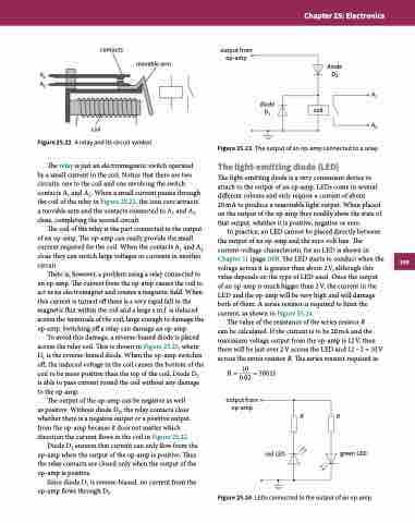
To avoid this damage, a reverse-biased diode is placed across the relay coil. This is shown in Figure 25.23, where D1 is the reverse-biased diode. When the op-amp switches off, the induced voltage in the coil causes the bottom of the coil to be more positive than the top of the coil. Diode D1 is able to pass current round the coil without any damage to the op-amp.
The output of the op-amp can be negative as well as positive. Without diode D2, the relay contacts close whether there is a negative output or a positive output from the op-amp because it does not matter which direction the current flows in the coil in Figure 25.22.
Diode D2 ensures that current can only flow from the op-amp when the output of the op-amp is positive. Thus the relay contacts are closed only when the output of the op-amp is positive.
Since diode D1 is reverse-biased, no current from the op-amp flows through D1.
Figure 25.23 The output of an op-amp connected to a relay.
The light-emitting diode (LED)
The light-emitting diode is a very convenient device to attach to the output of an op-amp. LEDs come in several different colours and only require a current of about
20 mA to produce a reasonable light output. When placed on the output of the op-amp they readily show the state of that output, whether it is positive, negative or zero.
In practice, an LED cannot be placed directly between the output of an op-amp and the zero-volt line. The current–voltage characteristic for an LED is shown in Chapter 11 (page 160). The LED starts to conduct when the voltage across it is greater than about 2V, although this value depends on the type of LED used. Once the output of an op-amp is much bigger than 2V, the current in the LED and the op-amp will be very high and will damage both of them. A series resistor is required to limit the current, as shown in Figure 25.24.
The value of the resistance of the series resistor R
can be calculated. If the current is to be 20 mA and the maximum voltage output from the op-amp is 12V, then there will be just over 2V across the LED and 12−2 = 10V across the series resistor R. The series resistor required is:
10
R = 0.02 = 500 Ω
output from op-amp
coil
A1 A2
red LED
R
Figure 25.24 LEDs connected to the output of an op-amp.
R
green LED
399
