
Page 414 - Physics Coursebook 2015 (A level)
P. 414
Cambridge International A Level Physics
6 The non-inverting amplifier in Figure 25.21 on page 398 has R1 = 15 kΩ, R2 = 5 kΩ and Vs = 10 V.
An a.c. signal of amplitude 0.20 V is applied to the input. Draw a single sketch graph which shows both the input
and the output voltage over two cycles of the input on the same axes. [3]
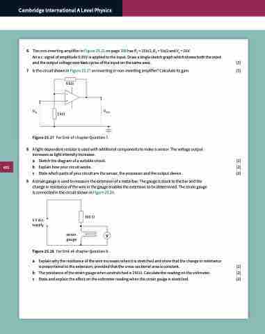
7 Is the circuit shown in Figure 25.27 an inverting or non-inverting amplifier? Calculate its gain. [3] 9 kΩ
– +
Vout
8 A light-dependent resistor is used with additional components to make a sensor. The voltage output increases as light intensity increases.
a Sketch the diagram of a suitable circuit. [2]
b Explain how your circuit works. [2]
c State which parts of your circuit are the sensor, the processor and the output device. [2]
9 A strain gauge is used to measure the extension of a metal bar. The gauge is stuck to the bar and the change in resistance of the wire in the gauge enables the extension to be determined. The strain gauge is connected in the circuit shown in Figure 25.28.
Vin 1 kΩ
Figure 25.27 For End-of-chapter Question 7.
5 V d.c. supply
300 Ω strain
gauge
V
Figure 25.28 For End-of-chapter Question 9.
a Explain why the resistance of the wire increases when it is stretched and show that the change in resistance
is proportional to the extension, provided that the cross-sectional area is constant. [2]
b The resistance of the strain gauge when unstretched is 150 Ω. Calculate the reading on the voltmeter. [2]
c State and explain the effect on the voltmeter reading when the strain gauge is stretched. [2]
402
