
Page 465 - Physics Coursebook 2015 (A level)
P. 465
Chapter 29: Alternating currents
QUESTIONS
2 The following questions relate to the graph of Figure 29.2.
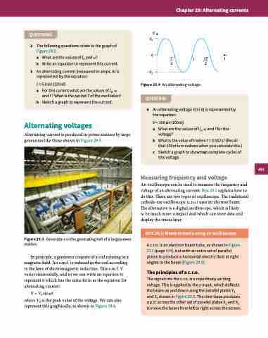
V V0
a WhatarethevaluesofI0andω? 0 T b Write an equation to represent this current. 2
3 An alternating current (measured in amps, A) is –V0 represented by the equation:
T 3T t 2
I = 5.0 sin (120πt)
a For this current what are the values of I0, ω
and f ? What is the period T of the oscillation?
b Sketch a graph to represent the current.
Alternating voltages
Alternating current is produced in power stations by large generators like those shown in Figure 29.3.
Figure 29.3 Generators in the generating hall of a large power station.
In principle, a generator consists of a coil rotating in a magnetic field. An e.m.f. is induced in the coil according to the laws of electromagnetic induction. This e.m.f. V varies sinusoidally, and so we can write an equation to represent it which has the same form as the equation for alternating current:
V = V0 sin ωt
where V0 is the peak value of the voltage. We can also represent this graphically, as shown in Figure 29.4.
Figure 29.4 An alternating voltage. QUESTION
4 An alternating voltage V (in V) is represented by the equation:
V = 300 sin (100πt)
a What are the values of V0, ω and f for this
voltage?
b What is the value of V when t = 0.002 s? (Recall
that 100πt is in radians when you calculate this.)
c Sketch a graph to show two complete cycles of
this voltage.
Measuring frequency and voltage
An oscilloscope can be used to measure the frequency and voltage of an alternating current. Box 29.1 explains how to do this. There are two types of oscilloscope. The traditional cathode-ray oscilloscope (c.r.o.) uses an electron beam. The alternative is a digital oscilloscope, which is likely
to be much more compact and which can store data and display the traces later.
BOX 29.1: Measurements using an oscilloscope
A c.r.o. is an electron beam tube, as shown in Figure 27.4 (page 424), but with an extra set of parallel plates to produce a horizontal electric field at right angles to the beam (Figure 29.5).
The principles of a c.r.o.
The signal into the c.r.o. is a repetitively varying voltage. This is applied to the y-input, which deflects the beam up and down using the parallel plates Y1 and Y2 shown in Figure 29.5. The time-base produces a p.d. across the other set of parallel plates X1 and X2 to move the beam from left to right across the screen.
453
