
Page 470 - Physics Coursebook 2015 (A level)
P. 470
Cambridge International A Level Physics
458
Transformers
The equation above is known as the turns-ratio equation for a transformer.
In words, the ratio of the voltages is equal to the
ratio of the number of turns of the transformer. For the transformer in Figure 29.12, a voltage of 1.0 V applied to the primary coil will result in an output of 2.0 V across the secondary coil; 50 V will give 100 V, and so on.
a
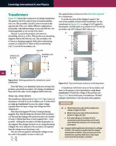
Figure 29.12 shows the construction of a simple transformer. The primary coil of N turns of wire is wound around an
p
iron core. The secondary coil of Ns turns is wound on the
opposite side of the core. (Many different configurations are possible, with different shapes of core and with the coils wound separately, or one on top of the other.)
The p.d. Vp across the primary coil causes an alternating current Ip to flow. This produces an alternating magnetic field in the soft iron core. The secondary coil
is thus in a changing magnetic field, and an alternating current Is is induced in it. There is thus an alternating e.m.f. Vs across the secondary coil.
Vp Vs
iron core
secondary coil,
Ns turns Vs
Is
Figure 29.12 Defining quantities for a simple iron-cored
transformer.
Note that there is no electrical connection between the primary coil and the secondary coil. Energy is transferred from one to the other via the magnetic field in the core.
Step-up, step-down
The transformer represented in Figure 29.12 has 5 turns on its primary coil and 10 on its secondary coil. It is described as a step-up transformer because the output voltage
is greater than the input voltage (the voltage has been ‘stepped up’).
How does this happen? We have 5 turns producing magnetic flux. This flux links the 10 turns of the secondary coil. Because flux linkage NΦ is proportional to the number of turns, it follows that there is more magnetic flux – twice as much – linking the secondary coil than the primary. As the magnetic flux changes (because we are using alternating voltages), the e.m.f. induced in the secondary coil is greater than the voltage across the primary coil.
We can write an equation relating the voltages across the coils to the number of turns in each coil:
Vs =Ns Vp Np
primary coil, Np turns
b
Vp
Ip
Vp Vs
Figure 29.13 Two transformers: a step-up, and b step-down.
A transformer with fewer turns on the secondary coil than on the primary coil is described as a step-down transformer. It lowers the voltage at the primary coil. Figure 29.13 shows both types of transformer. Worked example 3 shows how to use the turns-ratio equation.
QUESTIONS
11 a b c
What is the turns ratio of the transformer shown in Figure 29.13a?
What is the turns ratio of the transformer shown in Figure 29.13b?
If an alternating p.d. of value 10.0 V is connected across the primary coil of each, what will be the induced e.m.f. across each secondary?
12 A power station generates electricity at a voltage of 25 kV. This must be transformed for onward transmission at 400 kV. If the primary coil of the transformer used has 2000 turns, how many turnsmustthesecondarycoilhave?
