
Page 472 - Physics Coursebook 2015 (A level)
P. 472
Cambridge International A Level Physics
3
4
3
460
4
Rectification
Many electrical appliances work with alternating current. Some, like electrical heaters, will work equally well with d.c. or a.c. However, there are many appliances such as electronic equipment which require d.c. For these, the alternating mains must be converted to d.c. by the process of rectification.
A simple way to do this is to use a diode, which is a component that will only allow current to flow in one direction. Figure 29.15 shows a circuit for doing this, together with a graph to show the effect. You will see that the output voltage is always positive, but it goes up and down. This is still technically direct current, because the current only flows in one direction.
12
A a.c. supply ~
B
R Vout
Vout
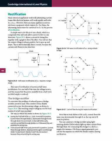
Figure 29.16 Full-wave rectification of a.c. using a diode
t
diode
bridge.
a.c. supply ~
load V resistor
out
2
+
aI R+A
Vout
Figure 29.15 Half-wave rectification of a.c. requires a single
diode.
This type of rectification is known as half-wave rectification. For one-half of the time the voltage is zero, and this means that the power available from a half-wave rectified supply is reduced.
The bridge rectifier
To overcome this problem of reduced power, a bridge rectifier circuit is used. This consists of four diodes connected across the alternating voltage, as shown in Figure 29.16. The resulting output voltage across the load resistor R is full-wave rectified.
The way in which this works is shown in Figure 29.17.
■■ During the first half of the a.c. cycle, terminal A is positive. Current flows through diode 2, downwards through R and through diode 3 to terminal B. In this half of the cycle, current cannot flow through diodes 1 or 4 because they are pointing the wrong way.
■■ In the second half of the cycle, terminal B is positive. Current flows through diode 4, downwards through R, and through diode 1 to terminal A. Diodes 2 and 3 do not conduct because they are pointing the wrong way.
–B
b
+B
R
t
1 –A
I
+
R
Figure 29.17 Current flow during full-wave rectification.
Note that in both halves of the cycle, current flows the same way (downwards) through R, so the top end of R must be positive.
You can construct a bridge rectifier using light- emitting diodes (LEDs) which light up when current flows through them. By connecting this bridge to a slow a.c. supply (for instance 1 Hz from a signal generator), you
can see the sequence in which the diodes conduct during rectification.
