
Page 473 - Physics Coursebook 2015 (A level)
P. 473
Chapter 29: Alternating currents
QUESTION
15 Explain why, when terminal B in Figure 29.17 is positive (during the second half of the cycle), the current flows through diodes 1 and 4, but not through diodes 2 and 3.
Smoothing
In order to produce steady d.c. from the ‘bumpy’ d.c.
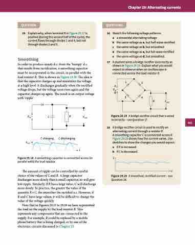
that results from rectification, a smoothing capacitor must be incorporated in the circuit, in parallel with the load resistor R. This is shown in Figure 29.18. The idea is that the capacitor charges up and maintains the voltage
at a high level. It discharges gradually when the rectified voltage drops, but the voltage soon rises again and the capacitor charges up again. The result is an output voltage with ‘ripple’.
QUESTIONS
Vin ~ C
C charging Vout
R
C discharging
Vout
B
34
R Vout Figure 29.19 A bridge rectifier circuit that is wired
incorrectly – see Question 17.
A bridge rectifier circuit is used to rectify an alternating current through a resistor R.
A smoothing capacitor C is connected across R. Figure 29.20 shows how the current varies. Use sketches to show the changes you would expect:
16
17
Sketch the following voltage patterns:
a a sinusoidal alternating voltage
b the same voltage as a, but half-wave rectified
c the same voltage as b, but smoothed
d the same voltage as a, but full-wave rectified
e the same voltage as d, but smoothed.
A student wires a bridge rectifier incorrectly as shown in Figure 29.19. Explain what you would expect to observe when an oscilloscope is connected across the load resistor R.
VA ~ in
12
t
a b
I
if R is increased if C is decreased.
18
Figure 29.18 A smoothing capacitor is connected across (in parallel with) the load resistor.
The amount of ripple can be controlled by careful choice of the values of C and R. A large capacitor discharges more slowly than a small capacitor, so will give less ripple. Similarly, if R has a large value, C will discharge more slowly. In practice, the greater the value of the quantity R × C, the smoother the rectified a.c. However, if R and C have large values, it will be difficult to change the value of the voltage quickly.
Note that in Figures 29.15 to 29.18 we have represented the load on the supply by the load resistor R. This represents any components that are connected to the supply. For example, R could be replaced by a mobile phone battery that is being charged, or by one of the electronic circuits discussed in Chapter 25.
t
Figure 29.20 A smoothed, rectified current – see Question 18.
461
