
Page 27 - Terrova Freshwater Trolling Motor Owner's Manual
P. 27
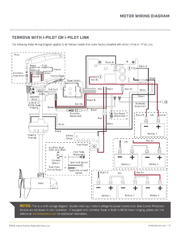
MOTOR WIRING DIAGRAM


         TERROVA WITH i-PILOT OR i-PILOT LINK

         The following Motor Wiring Diagram applies to all Terrova models that come factory installed with either i-Pilot or i-Pilot Link.


          i-Pilot

                                                                         Black M-
                     Brown    Fuse                                                             Black B-

                      Black M-       Ground
          Accessory            Brown
          Attachment   Red M+      Control Head
                                              Power Switch     Red B+                                  Black

                                  Coil Cord                         Red   Black       Red M+    White
                          i-Pilot Link
                            Cable
                     Universal                                                                 Black
                      Sonar                                 Black M-
                     or Built-in                                                             Accessory
                    MEGA Down                       Red M+                                   Attachment
                     Imaging     Brown
                                                               Brown
                                                Accessory                     Foot Pedal
                                                Attachment                    Attachment     Black B-  12v   Red B+
                                                                    Red
                                         White                            Black

                                      Black
                    Steering                  Battery                                                Battery 1
                    Housing                   Gauge
                                                                                     24v            Red B+
                                                     Foot Pedal
                                  AutoPilot (Red)
                                  Spot-Lock (Blue)
                                                   Foot Pedal
                                                   Attachment

                                    Constant
                                    (Green)      Spot-Lock Sensor                   Battery 1         Battery 2
                                  Foot Pedal
                                 Control Board  Speed Adjustment
                                                    Sensor           Black B-    36v          Red B+


                           Motor


                                                                      Battery 1       Battery 2        Battery 3


               NOTICE: This is a multi-voltage diagram. Double-check your motor's voltage for proper connections. Over-Current Protection
               Devices are not shown in this illustration.  If equipped with Universal Sonar or Built-in MEGA Down Imaging, please visit the
               website at minnkotamotors.com for additional information.


       ©2018 Johnson Outdoors Marine Electronics, Inc.                                                 minnkotamotors.com  |  27