
Page 3 - Z-Link Cervical System Booklet 2021
P. 3
Attach to the inserter instrument. Load implant onto the
inserter and clamp to the implant.
Step 5
Pack the implant with autograft
Use the graft loader and graft packer to facilitate loading of
the autograft. With the selected implant attached to the
insertion instrument, place the implant in the graft loader (note
that two graft loaders are available to match implant footprint)
fill the implant with autograft by loading autograft into the top
of the graft loader and packing into the implant with the graft
packer.
Step 6
Insert implant
With the implant mounted on the insertion instrument, gently
insert into the disc space towards its final position. A tamp is
available for tamping the implant into final position. Verify
the final implant position relative to the vertebral bodies.
A single midline x-ray marker in the PEEK spacer along with
the titanium interbody plate enables intraoperative
radiographic assessment of the implant position.
Step 7
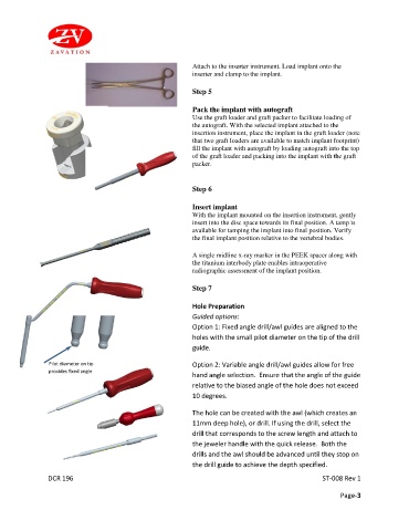
Hole Preparation
Guided options:
Option 1: Fixed angle drill/awl guides are aligned to the
holes with the small pilot diameter on the tip of the drill
guide.
Pilot diameter on tip Option 2: Variable angle drill/awl guides allow for free
provides fixed angle
hand angle selection. Ensure that the angle of the guide
relative to the biased angle of the hole does not exceed
10 degrees.
The hole can be created with the awl (which creates an
11mm deep hole), or drill. If using the drill, select the
drill that corresponds to the screw length and attach to
the jeweler handle with the quick release. Both the
drills and the awl should be advanced until they stop on
the drill guide to achieve the depth specified.
DCR 196 ST-008 Rev 1
Page-3