
Page 20 - Demo
P. 20
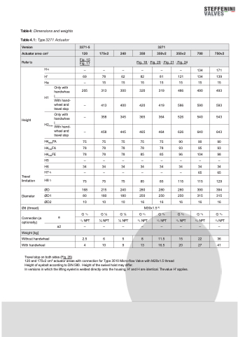
        Refer to
Height
Only with handwhee l
With hand- wheel and travel stop
Only with handwhee
Travel limitation
ØD Diameter ØD1 ØD2
Ød (thread)
Connection (a optionally)
a a2
Weight [kg]
H4)
H'
Ha
H1
H2 l
max Withhand-
wheel and travel stop
H4ratedFA H4maxFA H4maxFE H5
H6 H7 3)
H8 1)
Fig. 15 Fig. 17
–
69
–
205
–
–
–
75
78
78
–
34
–
75
168
80
10
G 1/8
1/8 NPT
–
–
78
15
313
413
358
458
75
78
78
–
34
–
75
215
180
10
G1⁄4
1⁄4 NPT
–
–
62
15
300
400
345
445
75
78
78
–
34
–
75
240
180
10
G1⁄4
1⁄4 NPT
–
Fig. 18 · Fig. 20 · Fig. 21 · Fig. 24
–
82
15
320
420
365
465
75
78
85
–
34
–
85
280
250
16
G 3/8
3/8 NPT
–
–
81
15
319
419
364
464
75
78
85
–
34
–
85
280
250
16
G 3/8
3/8 NPT
–
–
121
15
486
586
526
626
90
93
96
–
34
–
115
280
250
16
G 3/8
3/8 NPT
–
134
134
15
490
590
540
640
90
95
104
–
34
65
115
390
315
16
G 3/8
3/8 NPT
–
171
139
15
493
593
543
643
90
93
98
–
34
65
129
394
315
16
G 3/8
3/8 NPT
–
   Without handwheel 2.5 6 5 8 11.5 15 22 36
 With handwheel 4 10 9 13 16.5 20 27 41
                               M30x1.5 2)
Travel stop on both sides (Fig. 20)
120 and 175v2 cm2 actuator areas with connection for Type 3510 Micro-flow Valve with M20x1.5 thread
Height of eyebolt according to DIN 580. Height of the swivel hoist may differ.
In versions in which the lifting eyelet is welded directly onto the housing, H' and H are identical. Thevalue H' applies.
