
Page 21 - Demo
P. 21
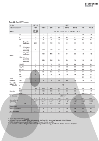
          Refer to
Fig. 16 Fig. 17
 Fig. 19 · Fig. 22 · Fig. 23 · Fig. 25 · Fig. 26
Height
Only with handwhee l
With hand- wheel and travel stop
Only with handwhee
Travel limitation
Yoke width (see Fig. 26)
H4)
H'
Ha
H1
H2 l
max Withhand-
wheel and travel stop
H4ratedFA H4maxFA H4maxFE H5
H6 H7 3)
H8 1) L
–
–
–
–
–
–
135
171
70
78
65
82
81
121
135
139
–
15
15
15
15
15
15
15
293
413
400
420
419
576
590
595
–
513
500
520
519
676
690
695
–
458
445
465
464
626
640
643
–
558
545
565
564
726
740
743
75
75
75
75
75
90
90
90
78
78
78
78
78
93
95
93
78
78
78
85
85
96
104
98
88
101
101
101
101
101
101
101
34
34
34
34
34
34
34
34
–
–
–
–
–
–
65
65
75
75
75
85
85
115
115
129
70
ØD
Diameter ØD1 ØD2
168
215
240
280
280
280
390
394
80
180
180
250
250
250
315
315
10
16
16
16
16
16
16
16
Ød (thread)
M30x1.5 2)
Connection (a a optionally)
a2
G 1/8
G1⁄4
G1⁄4
G 3/8
G 3/8
G 3/8
G 3/8
G 3/8
1/8 NPT
1⁄4 NPT
1⁄4 NPT
3/8 NPT
3/8 NPT
3/8 NPT
3/8 NPT
3/8 NPT
–
G 3/8
G 3/8
G 3/8
G 3/8
G 3/8
G 3/8
G 3/8
  Weight [kg]
 Without handwheel 3.2 10 9 12 15 19 26 40
 With handwheel 4.5 14 13 17 20 24 31 45
                                                    1) Travel stop on both sides (Fig. 23)
2) 120 and 175v2 cm2 actuator areas with connection for Type 3510 Micro-flow Valve with M20x1.5 thread
3) Height of eyebolt according to DIN 580. Height of the swivel hoist may differ.
4) In versions in which the lifting eyelet is welded directly onto the housing, H' and H are identical. Thevalue H' applies.
