
Page 22 - 959 17th Avenue South Spec Home Presentation
P. 22
3.9'
LANDSCAPE ARCHITECTURE
2780 S. Horseshoe Drive Suite 5
Naples, FL 34104
(239) 430-1661
4.6' Design@ALDinc.net
4.4' License LC26000259
Christian Andrea
7 S e Set
6'-0" 3.3'
4.6'
Channel Drain DRIVE
(Connect to Stormwater System)
13 1 S eeve
4'-4" 6'-4" License No. 1178
Copyright Architectural Land Design ©
5'-0" 4'-0"
4.3' 4'-4" 6'-4" 7'-10" 8'-1"
7'-10" 1 S eeve
27
3.5' POOL DECK 1 S eeve 17 DRIVE
7'-10" 7'-10" 7'-10" 6'-0"
4'-10" 7'-10" 7'-10"
3.6' 4'-10" FFE W/ Flooring): 8'-1" r t Set
1 S eeve
FFE (slab): 8'-0"
VANISHING EDGE 7'-5.5" POOL 7'-10" DRIVE 1 S eeve 14 6'-2" 17 3.5'
7'-8"
L:\21-102 Toscana 959 17th Ave S\ALD-Dwgs\21-102 - 0e.dwg, Plotted on 08.31.2019 / 11:04 PM by Christian Andrea
4'-10" 1 S eeve
17
4'-10" 7'-5.5" 7'-10" 7'-10" 7'-10"
5'-11.5" 6'-4" 6'-4" 5'-10"
5'-11" 5'-0"
SPA
POOL DECK
DRIVE
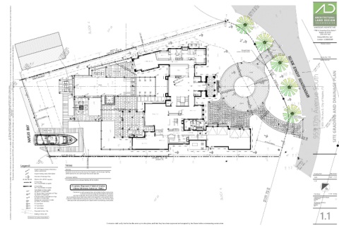
5'-8" 1 S eeve 22 959 17th Avenue South 959 17th Ave S ty e SITE GRADING AND DRAINAGE PLAN
5 e r Set 1 S eeve MOTOR COURT 5'-6"
authorization. Any deviations or inaccuracies need to be brought to the attention of the Owner immediately. * All base information has been provided by others, verification of setbacks, property lines, etc. need to be provided by others. * It is the Contractors responsibility to verify that he has the most current plan. * Contractor shall not scale from plan, use dimensions only. * These plans are the property of Architectural Land Design and may not be used or reproduced without This Document contains information proprietory to ARCHITECTURAL LAND DESIGN and no part of this drawing shall be reproduced or disclosed to others or used for any purpose other than that for which it was furnished, without prior written permission from ARCHITECTURAL LAND DESIGN. LOWER 43 1 S eeve
4'-0" POOL DECK 7'-11" 8'-0" 8'-1" 13 Channel Drain
15 Set 4'-9" 6'-3" 6'-4" 7'-10" (Connect to Stormwater System)
6'-6" 6'-0" DRIVE 4'-0"
6'-0"
3.5' 7'-6" 7'-0" 1 S eeve
OUTDOOR LIVING 6'-1" 23 1 S eeve
6'-0"
8'-0" 8'-1" 23 6'-1" 1 S eeve 13
WOOD DOCK 8'-1" 3.4'
7'-8" 6'-2"
7'-10"
4'-0" 7'-10" 7'-10" 5'-8" r t Set
3.8'
4.1' 3.4'
7 S e Set
Legend:
Legend: Notes
100'-0" Depicts Proposed Grade Information Sleeving
(Reflects Finished Grade)
All planter areas are to receive sleeves for irrigation and landscape lighting.
100.0' Depicts Existing Grade Information Sleeve sizes are to be 2 sizes larger than actual pipe size. Drawing Date: PM 07.20.21
Direction of Drainage Flow
Landscape Lighting Scale: 3/32" = 1'-0"
S eeves, Sch. 40 PVC (see plans)
It is anticipated that Landscape lighting will be installed.
21.102
6" Drain Pipe
(PVC or Smooth Walled Corrugated)
8" Drain Pipe A r e e re e t he r e
(PVC or Smooth Walled Corrugated)
e ther e te e S
t h Atr u r te
AD (See Detail 'A' on Details Sheet)
Contractor to verify property lines and setbacks before construction.
CB10 10" Round Grate Connected to 8" Pipe Contractor must have property lines staked and located, File Name: 21-102 - 0e.dwg
(See Detail 'B' on Details Sheet)
and must verify plan dimensions and field conditions are consistent.
CB8 8" Round Grate Connected to 6" Pipe Any Inconsistencies w/ these plans need to be reported to ALD and the Owner. Architectural Information Provided By:
(See Detail 'B' on Details Sheet)
Contractor shall verify that he has the most up to date plans, and that they have Company Name: ----
Downspout Connected to Gutter been approved and accepted by the Owner before commencing construction. File Name: ----
DS (See Detail 'C' on Details Sheet) Date: ----
Site Information Provided By:
CB9 9" Catch Basin Company Name: ----
File Name: ----
CB12 12" Catch Basin Date: ----
CB18 18" Catch Basin
Proposed Contour Line
1.1
1'
Existing Contour Line
Contractor to verify all quantities.
Contractor shall verify that he has the most up to date plans, and that they have been approved and accepted by the Owner before commencing construction.