
Page 3 - Earthworks Installed Sound 2015
P. 3
lustrate this, Figures 6a and 6b show a conventional microphones pickup area ute to acoustic feedback. Notice how the high frequencies track each other
(with full frequency response) from above and from either side of a podium. in the textbook perfect directional microphones shown in Figures 8a and 9a,
which will cause no peaks and dips or phase disparities.
(6a) (6b) At Last: More Gain Before Feedback
Figures 6a & 6b. Full frequency response cover- When comparing the textbook perfect directional microphone (Figure 9a)
age of a Conventional Directional Microphone to the Earthworks microphone (Figure 9b), notice how close together the
above (6a) and at the sides (6b) of a podium various high frequencies are from 0° to 270° and from 0° to 90°. See how
close the Earthworks microphone is to the textbook perfect microphone
In contrast, an Earthworks microphone will provide the full frequency re- shown in Figure 9a. Because of this very uniform polar response, an Earth-
sponse at any point around the microphone, out to nearly 90º on either side, works directional microphone will provide significantly more sound level
and also above and below. So, regardless of what position the orator speaks, before acoustic feedback. Now, compare the Earthworks microphone
they will be covered with the full frequency response of the microphone.
(a) Perfect Directional Microphone (b) Earthworks Directional Microphone
(7a) (7b) Figure 9. Differences Between a “Perfect” and an Earthworks Directional Microphone
shown in Figure 9b to the conventional microphone shown in Figure 8b.
Those who have used Earthworks High Definition Microphones™ in sound
reinforcement systems are always impressed with the significant increase in
sound level before acoustic feedback.
Figures 7a & 7b. Full frequency response cover- Conventional Microphones and
age of an Earthworks Directional Microphone Leakage of Sound from the Rear of the Microphone
from above (7a) and at the sides (7b) of a podium
In conference or meeting rooms it is important for a microphone to reject
In contrast, Figures 7a and 7b show the pickup area (with full frequency re- the sounds of other people speaking at the rear of the microphone. Conven-
sponse) of an Earthworks directional microphone, both above, and at the tional microphones exhibit this problem because they fail to adequately reject
sides of a podium. Notice the dramatic increase of the coverage area provid- sounds at the rear of the microphone.
ing the full frequency response of the microphone.
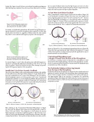
The Earthworks Solution to Rejecting Sounds
Insufficient Gain Before Acoustic Feedback from the Rear of the Microphone
One of the main problems with sound reinforcement systems is the inability Earthworks directional microphones are designed to have significantly more
to have sufficient sound level (gain) before feedback. Acoustic feedback prob- rejection of sounds at the rear of the microphone than conventional micro-
lems can be attributed to one or more of the following: (1) the microphone, phones. Notice in Figure 10a that a conventional microphone will only pro-
(2) the loudspeaker system, or (3) the acoustics of the room. Conventional vide approximately 18dB of rear rejection. In comparison, the Earthworks
microphones contribute to acoustic feedback problems through the lack of microphone (Figure 10b) will provide 32dB of rejection of sound at the rear of
uniformity in the polar response at different frequencies. For a directional the microphone, which is 14dB more than the conventional microphone, or
microphone to be “perfect,” all frequencies must exactly follow the textbook nearly twice as much.
perfect, heart-shaped pickup pattern shown in Figure 8a.
Approx 18dB
Rear Rejection
(a) Conventional
Directional
Microphone
(a) Perfect Cardioid Microphone (b) Conventional Cardioid Microphone Approx 32dB
Rear Rejection
Figure 8. Differences Between a Perfect and Conventional Cardioid Microphone (b) Earthworks
Directional
Now, referring to the “Conventional Directional Microphone” in Figure Microphone
8b, notice that the different high frequencies vary significantly in level (i.e.
4kHz, 16kHz and 20kHz). These disparities in level between the various Figure 10. Differences in Rear Rejection of Sound Between
high frequencies correspond to significant peaks or dips (increase or de- a Conventional Microphone and an Earthworks Microphone
crease in level) in the microphone’s overall frequency response, which also
creates phase problems. These peaks and dips and phase anomalies contrib-