
Page 38 - test
P. 38
Chapter 4 Managing the Switch Module
Connecting Devices to the Switch Module
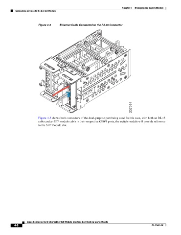
Figure 4-4 Ethernet Cable Connected to the RJ-45 Connector
237964
Figure 4-5 shows both connectors of the dual-purpose port being used. In this case, with both an RJ-45
cable and an SFP module cable in their respective GE0/1 ports, the switch module will provide reference
to the SFP module slot.
Cisco Connected Grid Ethernet Switch Module Interface Card Getting Started Guide
4-8 OL-23421-02