
Page 6 - April 2020_Neat
P. 6
6
April 2020 Return to Start
www.tswfl.org `Triumphs Live Page 6
On’
Tech Corner-continued
For our 4-cylinder Triumphs, the valves are adjusted ‘cold’. Anyone who has ever adjusted valves which need
to be adjusted ‘hot’ will know what a blessing this is! Stock clearance is .010” (ten one thousandths of an inch)
for both the intake and exhaust valves on most of our Triumphs, but for all cars and various camshafts it’s not
uncommon to have a different clearance specified for intakes vs exhausts. For example, early TR2’s equipped
with iron rocker pedestals specified clearances of .010” for the intake valves and .012” for the exhausts. To
determine which valve is which, see the description in method 2 below.
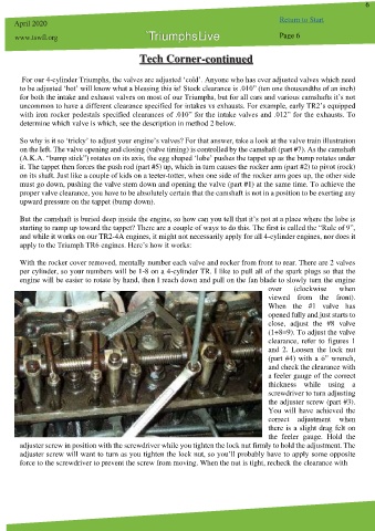
So why is it so ‘tricky’ to adjust your engine’s valves? For that answer, take a look at the valve train illustration
on the left. The valve opening and closing (valve timing) is controlled by the camshaft (part #7). As the camshaft
(A.K.A. “bump stick”) rotates on its axis, the egg shaped ‘lobe’ pushes the tappet up as the bump rotates under
it. The tappet then forces the push rod (part #5) up, which in turn causes the rocker arm (part #2) to pivot (rock)
on its shaft. Just like a couple of kids on a teeter-totter, when one side of the rocker arm goes up, the other side
must go down, pushing the valve stem down and opening the valve (part #1) at the same time. To achieve the
proper valve clearance, you have to be absolutely certain that the camshaft is not in a position to be exerting any
upward pressure on the tappet (bump down).
But the camshaft is buried deep inside the engine, so how can you tell that it’s not at a place where the lobe is
starting to ramp up toward the tappet? There are a couple of ways to do this. The first is called the “Rule of 9”,
and while it works on our TR2-4A engines, it might not necessarily apply for all 4-cylinder engines, nor does it
apply to the Triumph TR6 engines. Here’s how it works:
With the rocker cover removed, mentally number each valve and rocker from front to rear. There are 2 valves
per cylinder, so your numbers will be 1-8 on a 4-cylinder TR. I like to pull all of the spark plugs so that the
engine will be easier to rotate by hand, then I reach down and pull on the fan blade to slowly turn the engine
over (clockwise when
viewed from the front).
When the #1 valve has
opened fully and just starts to
close, adjust the #8 valve
(1+8=9). To adjust the valve
clearance, refer to figures 1
and 2. Loosen the lock nut
(part #4) with a ó” wrench,
and check the clearance with
a feeler gauge of the correct
thickness while using a
screwdriver to turn adjusting
the adjuster screw (part #3).
You will have achieved the
correct adjustment when
there is a slight drag felt on
the feeler gauge. Hold the
adjuster screw in position with the screwdriver while you tighten the lock nut firmly to hold the adjustment. The
adjuster screw will want to turn as you tighten the lock nut, so you’ll probably have to apply some opposite
force to the screwdriver to prevent the screw from moving. When the nut is tight, recheck the clearance with