
Page 236 - Foton Workshop Manual - Aumark (BJ1099)
P. 236
11-10 ENGINE CONTROL SYSTEM - ENGINE CONTROL SYSTEM
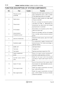
FUNCTION DESCRIPTION OF SYSTEM COMPONENTS
NO. Part Number Function
Optimize the control system according to the
Electronic control
1 1 signal provided by sensor, make it suitable
unit(ECM)
for the operating condition of the engine
Detect the rotation position and rotate speed
2 Speed sensor 1
of engine crankshaft
Provide crankshaft and camshaft position
information for ECM, i.e., differentiate the
3 Phase sensor 1
compression top dead center and exhaust
top dead center of crankshaft
Detect intake air temperature and air inflow,
4 Air flow meter 1
determine engine load
Detect the temperature and flow of air entering
Intake pressure/
5 1 into air cylinder, perform pressurize pressure
Temperature sensor
control
Detect the throttle position, adjust the throttle
6 Electronic throttle body 1
percentage
The pedal position signal is transformed to
7 Accelerator pedal 1 electrical signal. The throttle percentage is
adjusted indirectly
8 Ignition coil 4 Ignite gas mixture
9 Fuel pump 1 Transport fuel
10 Fuel injector 4 Eject fuel according to signal from ECM
Coolant temperature Detect the engine coolant temperature,
11 1
sensor confirm the engine operating conditions
Make the fuel vapor enter into canister
Canister purge control
12 1 according to digital pulse square wave of
valve
ECM
Control the oil flow of the engine, which
13 Intake VVT valve 1 flows towards the camshaft position actuator,
change air intake phase
Detect the oxygen concentration of exhaust
14 Front oxygen sensor 1
gas, confirm air-fuel ratio
Detect the oxygen concentration of exhaust
15 Rear oxygen sensor 1 gas, confirm whether the exhaust emission
reaches the standard
Page 236