Page 410 - Foton Workshop Manual - Aumark (BJ1099)
P. 410

12B-120                           ENGINE MECHANICAL - VALVE

           ADJUSTMENT


                                                      1.      Check the clearance of the valve(without
                                                              removing the timing mechanism )
                                                       (a).   Remove  the  camshaft  hood.(Refer
                                                              To"Chapter  12B  Engine  Mechanical
                                                              Systerm- Camshaft,Replacing")
                                                       (b).   Remove the spark plug with the spark plug
                                                              sleeve.


                                                      (c).   Insert a long bamboo stick or something
                                                              similar through the spark plug of No.1
                                                              cylinder.
                                                       (d).   Rotate the crankshaft and observe the
                                                              height of the bamboo stick. Stop rotating
                                                              when the bamboo stick reaches the highest
                                                              position.


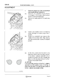
                                                       (e).   At this time, watch from the front to the
                                                              back and observe the protruding position
                                                              of the intake / exhaust camshaft of No.1
                                                              cylinder as shown in the fig. to identify the
                                                              piston is on the top dead center of the No.1
                                                              cylinder compression stroke.
                                                           NOTICE:
                                                      If the protruding position of the No.1 cylinder
                                                      camshaft is at the position shown in the fig., it
                                                      means that the piston is at the top dead center of
                                                      the No.1 cylinder compression stroke.


                                                                                                      Page 410
   405   406   407   408   409   410   411   412   413   414   415