
Page 20 - GP Fall 2020
P. 20
LEGENDS !26
vidually in a 25mm auto-polymerizing However, the use of the TA.XTPlus Texture toothbrush and a manual suction pump.
3
acrylic resin block (Caulk Orthodontic Analyzer did not rely on the load cell to ei-
Figure 1. TA.XTPlus Texture Analyzer with TA-317C Multiple Sample Vertical Friction
Resin; Dentsply) by using a silicone mold ther measure force or to apply a force. The The procedure was run in the form of two-
(Coltene-Whaledent, Inc.) that ensured the instrument was also not used in a way that body contact of bi-directional back-and-
precise horizontal alignment of the exter- necessitated knowledge or logging of the forth sliding movements in which a stylus
Wear Device in a plastic container filled with artificial saliva, which is fixed to the feed
nal surfaces of the disks, leaving the top absolute or relative position of the mounted runs against a flat surface with no lifting of
2 mm of each disk uncovered with resin. fixtures to the height of the base. The instru- the stylus (Figure 2 A). All enamel styluses,
Specimens were then randomly assigned to ment was used to stroke up and down 0.8 mesio-plalatal cusps, were scanned three-di-
mensionally using the SmartOptics Activity
groups (www.random.org). table of the cyclic loading machine. Movable upper arm of device with metallic weight
mm at 40 mm/second (Table 1) and to carry
880 Digital Scanner (Smart Optics Sensort-
the TA-317C Multiple Sample Vertical Fric-
Wear testing and measurement tion Wear Device. The instrument was not echnik GmbH). The scanner performed an
rods carried enamel styluses, while fixed lower arm carried ceramic and enamel disks’
The cyclic loading machine (TA.XTPlus used to measure or apply force during that automatic calibration, which was repeated
every time the specimens were scanned in
Texture Analyzer; Texture Technologies test; it just conducted the stroking according order to ensure the accuracy of the scan
Corp.) and a newly designed wear device to the test settings. The TA-317C Multiple results. The specimens were not powdered
specimens.
developed by the author, TA-317C Multiple Sample Vertical Friction Wear Device held based on the manufacturer’s recommenda-
Sample Vertical Friction Wear Device, were a set of static weights in a ‘normal force’ tion. The manufacturer claims the accuracy
used for wear stimulation, which allowed position which were translated to consistent of the scanner to be +/-20 µm. After com-
!26
testing of five specimens simultaneously but lateral ‘applied forces’ due to the shape of pletion of the wear-generating procedure,
independently with the parameters shown in the fixture and the rotational pivot of the de- opposing enamel wear for each tested spec-
Table I (Figure 1). The parameters were de- vice’s arm along the swing pin. imen was determined as the volume loss of
LEGENDS
termined based on previously published cri- its antagonist cusp.
teria and manufacturer’s standards. 35-37 The applied force (13.5 N) was a function of
Figure 1. TA.XTPlus Texture Analyzer with TA-317C Multiple Sample Vertical Friction
__________________________________ the static weights that were mounted on the Baseline data and follow-up scans were col-
Test Parameter Value fixture. That applied force was measured lected, superimposed by the software and
__________________________________
with the handheld scale for approximation, compared using the 3D digital inspection
Wear Device in a plastic container filled with artificial saliva, which is fixed to the feed
Sliding Movement 0.8 mm which is verifiable. The TA.XTPlus Texture software Qualify 2012 (Geomagic, Inc.).
Sliding Speed 40 mm/sec Analyzer has a stepper motor that takes dis- !27
table of the cyclic loading machine. Movable upper arm of device with metallic weight
Abrasive load per specimen 13.5 N (3 lb.) crete 1 mu steps. During the test sequence it This software generated color-mapped !27
models of each enamel cusp, and then
Cycle Frequency 2.5 Hz (150 cycles/min) moved 800 steps (0.8 mm) in each direction enamel cusp to detect geometrical changes. D, 3D Cusp Comparison to detect the
rods carried enamel styluses, while fixed lower arm carried ceramic and enamel disks’
Number of cycles 125000 for 125,000 cycles (total of 250,000), which aligned the models to detect the geometri-
cal changes that illustrate the wear caused
Contact Duration 0.04 Sec is equivalent to one year of clinical wear in enamel cusp to detect geometrical changes. D, 3D Cusp Comparison to detect the
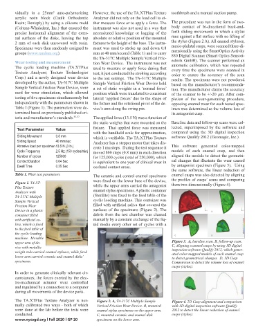
by antagonist specimen (Figure 3). Using
Dwell Time 0.35 Sec occlusal contact areas. volume loss of enamel cusps (stylus).
specimens.
the same software, the linear reduction of
volume loss of enamel cusps (stylus).
Table 1. Wear test parameters ! The ceramic and control enamel specimens enamel cusps was also detected by aligning
were fixed on the lower base of the device, the profiles of cusps’ scans and comparing
Figure 1. TA.XT- them two-dimensionally (Figure 4).
while the upper arms carried the antagonist
Plus Texture Figure 2. A, TA-317C Multiple Sample Vertical Friction Wear Device. B, mounted
Analyzer with enamel stylus specimens. A plastic container
TA-317C Multiple (Sterilite) was fixed to the feed table of the
cyclic loading machine. This container was
Sample Vertical enamel stylus specimens on the upper arm. C, mounted ceramic and enamel disks
Friction Wear filled with artificial saliva that covered the
Device in a plastic surfaces of the specimens (Figure 2). The
debris from the test chamber was cleaned
container filled specimens on the lower arm.
with artificial sa- manually by a constant exchange of the liq-
liva, which is fixed uid media every other set of cycles with a !
to the feed table of
the cyclic loading !
machine. Movable Figure 4. 2D Cusp alignment and comparison with 3D digital inspection software Qualify
!
upper arm of de- Figure 3. A, baseline scan. B, follow-up scan.
C, Aligning scanned cusps by using 3D digital
Figure 4. 2D Cusp alignment and comparison with 3D digital inspection software Qualify
vice with metallic 2012 to detect the linear reduction of enamel cusps (stylus).
weight rods carried enamel styluses, while fixed inspection software Qualify 2012, which gener-
ated color-mapped models of each enamel cusp
Figure 2. A, TA-317C Multiple Sample Vertical Friction Wear Device. B, mounted
lower arm carried ceramic and enamel disks’ to detect geometrical changes. D, 3D Cusp
2012 to detect the linear reduction of enamel cusps (stylus).
specimens. Comparison to detect the volume loss of enamel
enamel stylus specimens on the upper arm. C, mounted ceramic and enamel disks
cusps (stylus).
In order to generate clinically relevant cir-
specimens on the lower arm.
cumstances, the forces exerted by the elec-
tro-mechanical actuator were controlled
and regulated by a connection to a computer
during all movements of the device parts.
The TA.XTPlus Texture Analyzer is nor- Figure 2. A, TA-317C Multiple Sample Figure 4. 2D Cusp alignment and comparison
mally calibrated two ways - both of which Vertical Friction Wear Device. B, mounted with 3D digital inspection software Qualify
!
were done at the lab before the tests were enamel stylus specimens on the upper arm. 2012 to detect the linear reduction of enamel
conducted. C, mounted ceramic and enamel disk cusps (stylus).
www.nysagd.org l Fall 2020 l GP 20 specimens on the lower arm.
!
Figure 3. A, baseline scan. B, follow-up scan. C, Aligning scanned cusps by using 3D
Figure 5. Box-plots of enamel volume loss opposing ceramic and enamel disks’
!
digital inspection software Qualify 2012, which generated color-mapped models of each
specimens.
Figure 5. Box-plots of enamel volume loss opposing ceramic and enamel disks’
!
specimens.
Figure 3. A, baseline scan. B, follow-up scan. C, Aligning scanned cusps by using 3D
digital inspection software Qualify 2012, which generated color-mapped models of each