
Page 129 - McWane Poles Sales Manual 2024
P. 129
Sales Manual • 2024
129
Load Cycle
Load
Measured
(kips)
Load
Adjusted
(kips)
Deflection
Measured
(inches)
Deflection
Adjusted
(inches)
1 0 0 0 0
1 .52 0.50 10 9.7
1 1.00 0.97 21 20.4
1 1.68 1.63 33 32.0
1 2.00 1.94 39 37.8
1 2.64 2.56 49 47.5
1 3.08 2.99 57 55.3
1 3.48 3.38 64 62.1
1 4.04 3.92 72 69.8
1 4.52 4.38 83 80.5
1 5.04 4.89 91 88.3
1 5.48 5.32 98 95.1
1 5.64 5.48 102 98.9
1 0 0 8 7.8
2 0.56 0.54 15 14.6
2 1.00 0.97 23 22.3
2 1.64 1.59 30 29.1
2 1.96 1.90 37 35.9
2 2.64 2.56 49 47.5
2 2.96 2.87 55 53.4
2 3.64 3.53 65 63.1
2 4.08 3.96 71 68.9
2 4.60 4.46 78 75.7
2 5.04 4.89 84 81.5
2 5.56 5.39 92 89.2
2 6.04 5.86 99 96.0
2 6.52 6.32 109 105.7
2 7.12 6.91 119 115.4
2 7.56 7.33 127 123.2
2 8.04 7.80 136 131.9
2 8.48 8.23 149 144.5
2 8.80 8.54 162 157.1
2 9.00 8.73 170 164.9
2 9.44 9.16 192 186.2
2
9.60 (failed
at 3rd joint
from tip and
compression at
ground line)
9.31 204 197.9
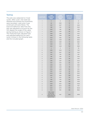
Testing:
The pole was subjected to 2 load
cycles. After cycle 1, the load was
released and residual tip movements
were recorded. Load cycle 2 was
continued until pole failure. The
load and deflection data from the
test was adjusted to account for the
14.5 degree line angle of the cable
during testing as shown in Figure 1.
The measured load, adjusted load
and adjusted deflection for each
cycle is shown in the following table
and the included graph:
