
Page 99 - Green - Maritime Archaeology: A Technical Handbook. 2nd ed
P. 99
a
78 Maritime Archaeology: A Technical Handbook, Second Edition
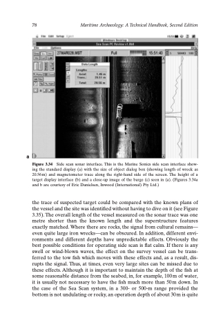
Figure 3.34 Side scan sonar interface. This is the Marine Sonics side scan interface show- ing the standard display (a) with the size of object dialog box (showing length of wreck as 20.56 m) and magnetometer trace along the right-hand side of the screen. The height of a target display interface (b) and a close-up image of the barge (c) seen in (a). (Figures 3.34a and b are courtesy of Eric Danielsen, Inwood (International) Pty Ltd.)
the trace of suspected target could be compared with the known plans of the vessel and the site was identified without having to dive on it (see Figure 3.35). The overall length of the vessel measured on the sonar trace was one metre shorter than the known length and the superstructure features exactly matched. Where there are rocks, the signal from cultural remains— even quite large iron wrecks—can be obscured. In addition, different envi- ronments and different depths have unpredictable effects. Obviously the best possible conditions for operating side scan is flat calm. If there is any swell or wind-blown waves, the effect on the survey vessel can be trans- ferred to the tow fish which moves with these effects and, as a result, dis- rupts the signal. Thus, at times, even very large sites can be missed due to these effects. Although it is important to maintain the depth of the fish at some reasonable distance from the seabed, in, for example, 100 m of water, it is usually not necessary to have the fish much more than 50 m down. In the case of the Sea Scan system, in a 300- or 500-m range provided the bottom is not undulating or rocky, an operation depth of about 30 m is quite
