
Page 148 - The Complete Rigger’s Apprentice
P. 148
so the load on each leg is 1,127.5 pounds (531.5 kg). worth considering that some members of the crew
You can also say that the total load varies with the might weigh more than 150 pounds (68 kg), and
sine of the angle. The angle here is about 3.814 that the wire might not be 100 percent efficient, and
degrees. The sine of this angle is .066519, and 150 that the fasteners that anchor the lifeline are mostly
divided by .066519 is, again, about 2,255. subjected to a shearing force, which they cannot
In practice the formulas are more precise, and withstand as stoutly as they can an upward pull. In
the stress diagram is handier for showing the effects other words, the formula or diagram is just a start-
of changes in configuration. ing point.
But let’s come back to that lifeline. Our calcula- Taking this into account, it’s clear that this life-
tions were based on a static, sustained load of 150 line is ironically named. We need to increase wire
pounds (68 kg), the weight of a lean crewmember. strength, reduce tension on the wire, or both.
Under those conditions we have a factor of safety of Let’s start by reducing the tension. As shown
less than 2—marginal at best. Now consider that in in Figure 5-9, lengthening the wire until it deflects
real life, that 150-pound (68 kg) load will come on 18 inches (457 mm) results in a load on each leg
abruptly when the crewmember falls or is washed of about 750 pounds (341 kg). By increasing the
across the deck. In this “shock load” circumstance, deflection, you reduce the leverage the load exerts
the momentum from the load can easily double or on the wire’s ends. You can keep on increasing
triple the load arrived at by our calculations. It’s also deflection until the two sides are nearly parallel.
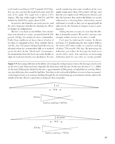
Figure 5-9. Increasing deflection in the lifeline (decreasing the resting tension) reduces the leverage a load exerts
on the wire’s ends. Expressed more elegantly: the load varies with the sine. In this case the sine is ⁄15 = .0666.
1
So the load (150 pounds) divided by the sine = approximately 2,250 pounds, or half of that on each leg. With a
two-foot deflection, there would be half that. Note that, in the real world of lifelines, it is rare to have an unmod-
erated impact load, as in someone hurtling through the air and fetching up at maximum velocity, right in the
middle of the line. But it’s a good idea to design for that eventuality.
2 ft
30 ft
150 lbs
load on each leg = 560 lbs
18 inches
30 ft
150 lbs
load on each leg = 750 lbs
127