
Page 196 - Airplane Flying Handbook
P. 196
should raise the nose; and when the airspeed is too low, lower the nose. If the pitch attitude is raised too high, the airplane settles rapidly
due to a slow airspeed and insufficient lift. For this reason, the pilot should never try to stretch a glide to reach the desired landing spot.
7806
Note that certain single-engine turboprop airplanes experience an excessive rate of descent if the power is set to flight idle. In some cases,
if the powerplant failed, the manufacturer's checklist calls for feathering the propeller during a power-off glide. During flight training
in these airplanes, the propeller is not feathered as would be the case in an emergency or true power-off glide. During training and pilot
certification, where the manufacturer's checklist calls for propeller feathering in a power-off situation, the pilot should set sufficient
power to provide the performance that would be expected with the propeller feathered.
1125
Uniform approach patterns, such as the 90° or 180° power-off approaches, are described further in this chapter. Practicing these approaches
provides a pilot with a basis on which to develop judgment in gliding distance and in planning an approach. While square patterns
demonstrate good planning, they are not required and may not be appropriate for every approach. For example, when conditions are not
as expected, pilots may need to dog-leg away from the runway on base or dog-leg toward the runway on base. Pilots may use S-turns,
slips, early or late extension of flaps, reduce airspeed below best glide, or increase airspeed slightly above best glide in a headwind in
order to stabilize the remaining approach, to reach the desired aiming point at an appropriate speed, and to touch down where planned.
Note that selection of the runway numbers as the touchdown point does not provide a safety cushion in case of a mechanical problem or
misjudgment. Selecting a point farther down the runway establishes an increased safety margin.
1126
The basic procedure in these approaches involves closing the throttle at a given altitude and gliding to a key position. Starting with the
same energy (airspeed and height) each time the throttle is closed, makes the maneuver more predictable. The key position, like the
pattern itself, is not the primary objective; it is merely a convenient point in the air from which the pilot can judge what to do such that
the landing occurs at or just beyond the desired point. The selected key position should be one that is appropriate for the available altitude
and the wind condition. From the key position, the pilot should constantly evaluate the situation.
1127
It should be emphasized that, although accurate spot touchdowns are important, safe and properly executed approaches and landings are
vital. A pilot should never sacrifice a good approach or landing just to land on the desired spot.
90° Power-Off Approach
1128
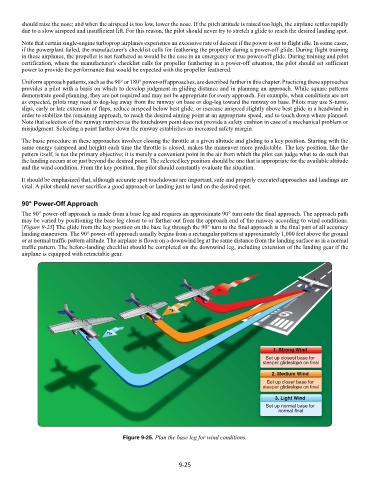
The 90° power-off approach is made from a base leg and requires an approximate 90° turn onto the final approach. The approach path
may be varied by positioning the base leg closer to or farther out from the approach end of the runway according to wind conditions.
[Figure 9-25] The glide from the key position on the base leg through the 90° turn to the final approach is the final part of all accuracy
landing maneuvers. The 90° power-off approach usually begins from a rectangular pattern at approximately 1,000 feet above the ground
or at normal traffic pattern altitude. The airplane is flown on a downwind leg at the same distance from the landing surface as in a normal
traffic pattern. The before-landing checklist should be completed on the downwind leg, including extension of the landing gear if the
airplane is equipped with retractable gear.
1129
Figure 9-25. Plan the base leg for wind conditions.
1130
9-25