
Page 239 - Airplane Flying Handbook
P. 239
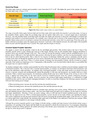
Governing Range


        The blade angle range for   constant-speed propellers varies from about 11.5° to 40°. The higher the speed of the airplane, the greater
        the blade angle range.   [Figure 12-8]


                                       Figure 12-8. Blade angle range (values are approximate).


        The range of   possible blade angles between high and low blade angle pitch stops define the propeller’s governing range. As long as


        the  propeller's    blades  operate  within  the  governing  range  and  not  against either  pitch stop, a constant engine rpm     is maintained.


        However,   once the propeller blades reach their pitch-stop limit, the engine rpm increases or decreases with changes in airspeed and


        propeller   load similar to a fixed-pitch propeller. For example, once a specific rpm is selected, if the airspeed decreases enough, the


        propeller   blades reduce pitch in an attempt to maintain the selected rpm until they contact their low pitch stops. From that point, any


        further   reduction in airspeed causes the engine rpm to decrease. Conversely, if the airspeed increases, the pitch angle of the propeller


        blades increase until the high   pitch stop is reached. The engine rpm then begins to increase.


        Constant-Speed Propeller Operation

                                                                                                         r


                                                                                                        o


        The engine     is started with the propeller control in the low pitch/high rpm position. This position reduces the load     drag of the


        propeller   and the result is easier starting and warm-up     f the engine.   During warm-up,   the propeller   blade changing mechanism is


                                                      o


        operated   slowly and smoothly through a full cycle. This is done by moving the propeller control (with the manifold pressure set to


                              to


        produce   about 1,600   rpm)     the high pitch/low rpm position,   allowing the rpm to stabilize, and then moving the propeller control


        back     the low pitch takeoff position.   This is done for   two   reasons: to determine whether the system is operating correctly and to


             to


        circulate fresh   warm oil through the propeller governor system. Remember the oil has been trapped in the propeller cylinder since the


        last   time the engine was shut down. There is a certain amount of leakage from the propeller cylinder, and the oil tends to congeal,


        especially     if the outside air temperature is low. Consequently, if the propeller is not exercised before takeoff, there is a possibility that

        the engine may   over-speed on takeoff.


        An   airplane equipped with a constant-speed propeller has better takeoff performance than a similarly powered airplane equipped with


        a fixed-pitch   propeller. This is because with a constant-speed propeller, an airplane can develop its maximum rated horsepower (red


        line on   the tachometer) while motionless. An airplane with a fixed-pitch propeller, on the other hand, needs to accelerate down the


        runway     increase airspeed  and  aerodynamically unload  the propeller  so  that rpm and horsepower can steadily build up     their


                                                                                                             to
               to


        maximum.   With a constant-speed propeller, the tachometer reading should come up to within 40 rpm of the red line as soon as full


        power     is  applied  and  remain  there  for  the  entire  takeoff.  Excessive  manifold  pressure  raises  the  cylinder  combustion  pressures,


        resulting     in  high  stresses  within  the  engine.  Excessive  pressure  also  produces  high-engine  temperatures.  A  combination  of  high


        manifold   pressure and low rpm can induce damaging detonation. In order to avoid these situations, the following sequence should be


        followed   when making power changes.


            ⦁ When   increasing power, increase the rpm first and then the manifold pressure


            ⦁ When   decreasing power, decrease the manifold pressure first and then decrease the rpm


        The cruise power   charts in the AFM/POH should be consulted when selecting cruise power settings. Whatever the combinations of


        rpm   and manifold pressure listed in these charts—they have been flight tested and approved by engineers for the respective airframe


        and   engine manufacturer. Therefore,     if there are power settings, such as 2,100 rpm and 24 inches manifold pressure in the power


        chart, they   are approved   for   use.   With a constant-speed   propeller, a power descent can be made without over-speeding the engine.


        The system   compensates for the increased airspeed of the descent by increasing the propeller blade angles. If the descent is too rapid


        or     is being made from a high altitude, the maximum blade angle limit of the blades is not sufficient to hold the rpm constant. When


        this   occurs, the rpm is responsive to any change in throttle setting.


        Although   the governor responds quickly to any change in throttle setting, a sudden and large increase in the throttle setting causes a


        momentary   over-speeding of the engine until the blades become adjusted to absorb the increased power. If an emergency demanding


        full power   should arise during approach, the sudden advancing of the throttle causes momentary over-speeding of the engine beyond


        the rpm   for which the governor is adjusted.

                                                            12-8