
Page 310 - Airplane Flying Handbook
P. 310
Airplane Flying Handbook (FAA-H-8083-3C)
Chapter 16: Transition to Jet-Powered Airplanes
Introduction
This chapter contains an overview of jet-powered airplane operations. The information contained in this chapter provides a useful
preparation for, and a supplement to, structured jet airplane qualification training. This chapter provides information on major
differences a pilot may encounter when transitioning to jet-powered airplanes. The major differences between jet-powered airplanes
and piston-powered airplanes have been addressed in several distinct areas: differences in aerodynamics, systems, and pilot operating
procedures. For airplane-specific information, a pilot should refer to the FAA-approved Airplane Flight Manual for that airplane.
Ground Safety
Stepping out on the ramp in the vicinity of jet airplanes requires special caution. There is no propeller to indicate visually whether a
to
jet engine is running. It is easy inadvertently stray into danger since, even at idle, jet engines are a threat. Enough air is being
sucked into the intake to pull a nearby person into the fan. The air coming from the exhaust is hot and moving fast enough to blow a
person down.
Pilots operating jet-powered airplanes should exercise caution during taxi and when adding power to start moving. Adding too much
power can pull damaging debris up off the ground or cause damage well behind the aircraft. Jet blast when taxiing into parking areas
may affect any loose ground equipment.
Jet Engine Basics
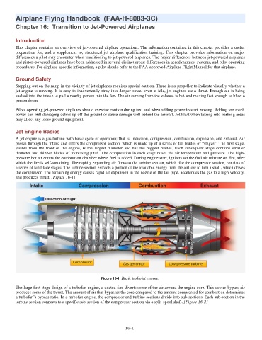
A jet engine is a gas turbine with basic cycle of operation; that is, induction, compression, combustion, expansion, and exhaust. Air
passes through the intake and enters the compressor section, which is made up of a series of fan blades or “stages.” The first stage,
visible from the front of the engine, is the largest diameter and has the biggest blades. Each subsequent stage contains smaller
diameter and thinner blades of increasing pitch. The compression in each stage raises the air temperature and pressure. The high-
pressure hot air enters the combustion chamber where fuel is added. During engine start, igniters set the fuel air mixture on fire, after
which the fire is self-sustaining. The rapidly expanding air flows to the turbine section, which like the compressor section, consists of
a series of fan blade stages. The turbine section extracts a portion of the available energy from the airflow to turn a shaft, which drives
the compressor. The remaining energy causes rapid air expansion in the nozzle of the tail pipe, accelerates the gas to a high velocity,
and produces thrust. [Figure 16-1]
Figure 16-1. Basic turbojet engine.
o
The large first stage design f a turbofan engine, a ducted fan, diverts some of the air around the engine core. This cooler bypass air
produces some of the thrust. The amount of air that bypasses the core compared to the amount compressed for combustion determines
a turbofan’s bypass ratio. In a turbofan engine, the compressor and turbine sections divide into sub-sections. Each sub-section in the
turbine section connects to a specific sub-section of the compressor section via a split-spool shaft. [Figure 16-2]
16-1