
Page 328 - Airplane Flying Handbook
P. 328
Planned descent speed will affect the position of the planned top of descent point. [Figure 16-15] In this example, both jets fly past
point X at the same cruise speed and altitude with plans to arrive at point Y at 10,000 feet and 250 knots. In both cases, the aircraft
set up
would then be in a position to a continued descent. The 250-knot descent requires a few miles for deceleration and gives a
shallower descent path. The 300-knot descent allows staying at altitude longer, descending at a steeper angle, and then leveling off to
slow 250 knots. The jet that descended at 300 knots arrives first at point Y but burns more fuel. While not depicted, an inefficient
to
descent plan would start the descent at point X, maintain 300 knots, and require power to maintain that airspeed on a shallow descent
path.
Figure 16-15. Effect of speed on descent path.
Descending prior to the planned TOD point will increase time to destination and fuel consumption. When given a descent clearance
the planned TOD, it is acceptable to ask ATC if the descent can be done at the pilot’s discretion. If authorized to do so, this
prior to
option allows for maintaining speed and altitude until reaching the calculated top of descent point. If an immediate descent is
required, a descent at 1,000 feet per minute is usually acceptable until reaching the desired path. If a descent clearance has not been
received by the planned TOD point, a speed reduction will reduce the airplane's kinetic and total energy while potential energy
remains constant. When the clearance is received, a slightly steeper descent at the onset allows for a desired increase in kinetic energy
at the expense of altitude and an appropriate descent rate such that the airplane follows the steeper desired path with acceptable
energy distribution.
Jet Engine Landing
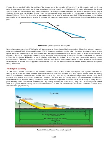
14 CFR part 25, section 25.125 defines the horizontal distance needed in order to land a jet airplane. The regulation describes the
landing profile as the horizontal distance required to land and come to a complete stop from a point 50 feet above the landing
surface. Manufacturers determine the landing distance on a dry, level runway at standard temperatures without using thrust
reversers, auto brakes, or auto-land systems as a baseline. The pilot uses the landing weight and environmental conditions to
determine the actual expected landing requirement based on the FAA-approved data in the AFM. As an accepted safety practice,
pilots normally add a 40% cushion for landing on a dry runway. Dividing the usable runway length by 1.67 should give a number
equal to or greater than the landing distance calculated from AFM data. For a wet runway, the distance should be increased by an
additional 15%. [Figure 16-16]
Figure 16-16. FAR landing field length required.
16-19