
Page 182 - Hydra-matic 6 Speed RWD Technician's Guide (October 2005)
P. 182
100
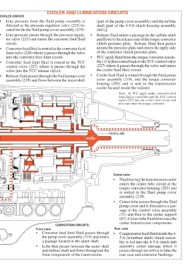
LUBRICATION POINTS
COOLER
CENTER
LUBE FROM
Figure 95
FRONT LUBE FLUID
FROM CONVERTER FEED
REAR LUBE (COMP FEED)
OIL PUMP
ASSEMBLY
•
•
•
•
•
circuit.
COOLER CIRCUIT:
•
•
Front Lube
valve into the TCC release circuit.
into the converter feed limit circuit.
Converter feed fluid is routed to the converter feed
Converter feed limit fluid is routed to the TCC
assembly (219) and flows between the stator shaft
Release fluid passes through the fluid pump cover
limit valve (220) where it passes through the valve
control valve (227) where it passes through the
tor valve (223) and enters the converter feed fluid
Line pressure passes through the pressure regula-
cated inside the fluid pump cover assembly (219).
Line pressure from the fluid pump assembly is
directed to the pressure regulator valve (223) lo-
LUBRICATION CIRCUITS:
•
•
•
a passage located in the stator shaft.
front components of the transmission.
(441)].
Converter feed limit fluid passes through
the pump cover assembly (219) and enters
Lube then passes between the stator shaft
and turbine shaft and flows throughout the
•
•
•
REAR LUBE
Rear Lube
COOLER AND LUBRICATION CIRCUITS
Center Lube
the cooler feed fluid circuit.
assembly (219).
cooler located inside the radiator.
of the converter clutch pressure plate.
does not enter the torque converter.
center transmission components.
rear case and extension bushings.
around the pressure plate and enters the apply side
Release fluid enters a passage in the turbine shaft
(227) where it passes through the valve and enters
clutch pressure plate. Release fluid then passes
(part of the pump cover assembly) and the turbine
shaft [part of the 4-5-6 clutch housing assembly
and flows to the release side of the torque converter
Cooler feed fluid is routed through the fluid pump
valve (227) into the cooler feed circuit and
bly (1) is then routed back to the TCC control valve
limit fluid is routed through the TCC control
Note: In TCC apply mode, converter feed
housing (203) and is sent to the transmission
cover assembly (219), into the torque converter
TCC apply fluid from the torque converter assem-
Compensator feed fluid inside the 4-
assembly center passage where it
passes through an orifice to lube the
5-6 (w/turbine shaft) clutch assem-
bly is fed into the 4-5-6 clutch hub
torque converter housing (203) and
is routed to the fluid pump cover
Fluid leaving the transmission cooler
enters the center lube circuit at the
Center lube passes through the fluid
(21) and then to the center support
(67). Center lube fluid lubricates the
pump cover and is directed to a pas-
sage in the control valve assembly