Page 8 - Hydra-matic 6 Speed RWD Technician's Guide (October 2005)
P. 8

UNDERSTANDING THE GRAPHICS


                                                  FLUID PUMP
                                 TORQUE             COVER
                                CONVERTER          ASSEMBLY
                                 HOUSING             (219)
                                   (203)
               TORQUE
             CONVERTER
              ASSEMBLY                                                                            TRANSMISSION
                 (1)                                                                                  CASE
                                                                                                    ASSEMBLY
                                                                                                       (7)


                                                                                                    CONTROL
                                                                                                      VALVE
                                                                                                    ASSEMBLY
                                                                                                       (21)


                                                                                                      FLUID
                                                                                                     FILTER
                                                                                                    ASSEMBLY
                                                                                                       (26)
                                                                        FLUID
                                                                        PAN
                                                                      ASSEMBLY
                                                                        (29)


                                                         Figure 2
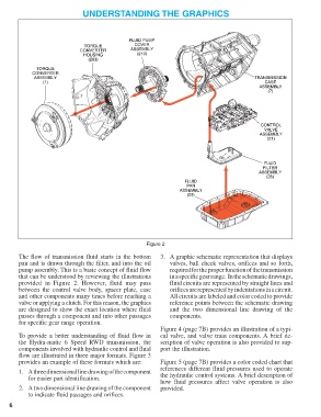
        The flow of transmission fluid starts in the bottom   3. A graphic schematic representation that displays
        pan and is drawn through the filter, and into the oil     valves, ball check valves, orifices and so forth,
        pump assembly. This is a basic concept of fluid flow      required for the proper function of the transmission
        that can be understood by reviewing the illustrations     in a specific gear range.  In the schematic drawings,
        provided in Figure 2. However, fluid may pass             fluid circuits are represented by straight lines and
        between the control valve  body, spacer plate, case       orifices are represented by indentations in a circuit.
        and other components many times before reaching a         All circuits are labeled and color coded to provide
        valve or applying a clutch. For this reason, the graphics  reference points between the schematic drawing
        are designed to show the exact location where fluid       and the two dimensional line drawing of the
        passes through a component and into other passages        components.
        for specific gear range operation.
                                                              Figure 4 (page 7B) provides an illustration of a typi-
        To provide a better understanding of fluid flow in    cal valve, and valve train components. A brief de-
        the Hydra-matic 6 Speed RWD transmission, the         scription of valve operation is also provided to sup-
        components involved with hydraulic control and fluid  port the illustration.
        flow are illustrated in three major formats. Figure 3
        provides an example of these formats which are:       Figure 5 (page 7B) provides a color coded chart that
                                                              references different fluid pressures used to operate
        1. A three dimensional line drawing of the component
            for easier part identification.                   the hydraulic control systems. A brief description of
                                                              how fluid pressures affect valve operation is also
        2. A two dimensional line drawing of the component    provided.
            to indicate fluid passages and orifices.

     6
   3   4   5   6   7   8   9   10   11   12   13