
Page 96 - Hydra-matic 6 Speed RWD Technician's Guide (October 2005)
P. 96
68
(51)
ASSEMBLY
1-2-3-4 AND 3-5
REVERSE CLUTCH
➤
➤
➤
CLUTCH
APPLIED
3-5 REVERSE
(64)
3
2-6 AND
DRIVING
ASSEMBLY
3-5 REVERSE
CLUTCH HUB
APPLIED
REVERSE
(52)
INPUT
DRIVEN
CARRIER
➤
ASSEMBLY
➤
(53)
HELD
INPUT
SUN GEAR
(487)
➤
DRIVING
➤
OUTPUT CARRIER
FRONT SUN GEAR
6
(68)
INPUT
DRIVING
Figure 63
OUTPUT
CARRIER
ASSEMBLY
INTERNAL GEAR
➤
➤
(68)
➤
CARRIER
OUTPUT
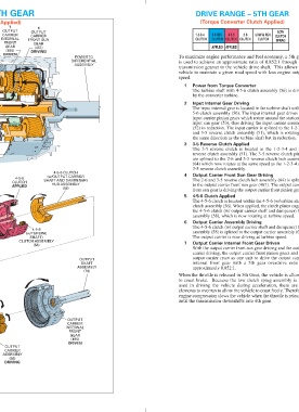
➤ ➤ ➤ ➤ ➤ ➤ DRIVEN (495) DRIVING GEAR DRIVING FRONT (1) APPLIED CLUTCH GEAR INTERNAL CONVERTER CLUTCH INTERNAL CARRIER TORQUE 4-5-6 3-5 INPUT OUTPUT POWER FROM 5 2 7 1 (T orque Converter Clutch Applied) DRIVE RANGE – 5TH GEAR
DRIVING
ASSEMBLY
4-5-6
CLUTCH
APPLIED
➤
➤ 1 speed. vehicle to maintain a given road speed with less engine output transmission gearset to the vehicle drive shaft. This allows the ASSEMBLY is used to achieve an approximate ratio of 0.852:1 through the DIFFERENTIAL POWER TO DRIVING (487) APPLIED GEAR SPRAG FRONT SUN CLUTCH CLUTCH CARRIER 1-2-3-4 OUTPUT 4 (Torque Converter Clutch Applied) DRIVE RANGE – 5TH GEAR
(56)
4-5-6
➤
SHAFT)
(w/TURBINE
CLUTCH ASSEMBLY
➤
(58)
4-5-6 CLUTCH
(495)
HUB ASSEMBLY
GEAR
FRONT
DRIVEN
OUTPUT
CARRIER
(w/OUTPUT CARRIER
INTERNAL
SHAFT AND DAMPENER)
(70)
SHAFT
OUTPUT
ASSEMBLY
2
3
4
7
5
6
3-5 REV.
CLUTCH
4-5-6
4-5-6 Clutch Applied
approximately 0.852:1.
CLUTCH
APPLIED
by the converter turbine.
3-5 reverse clutch assembly.
2-6
Input Internal Gear Driving
3-5 Reverse Clutch Applied
CLUTCH
Power from Torque Converter
Output Carrier Assembly Driving
CLUTCH
LOW & REV.
until the transmission downshifts into 4th gear.
Output Carrier Front Sun Gear Driving
Output Carrier Internal Front Gear Driven
LOW
The output carrier is now driving at turbine speed.
assembly (58), which is now rotating at turbine speed.
the same direction as the turbine shaft but in reduction.
The 3-5 reverse clutch is located in the 1-2-3-4 and 3-5
used in driving the vehicle during acceleration, there are no
and 3-5 reverse clutch assembly (51), which is rotating in
When the throttle is released in 5th Gear, the vehicle is allowed
to coast brake. Because the low clutch sprag assembly is not
(52) in reduction. The input carrier is splined to the 1-2-3-4
elements to overrun to allow the vehicle to coast freely. Therefore,
to the output carrier front sun gear (487). The output carrier
engine compression slows the vehicle when the throttle is released
The 2-6 and 3-5 reverse clutch hub assembly (64) is splined
front sun gear is driving the output carrier front pinion gears.
reverse clutch assembly (51). The 3-5 reverse clutch plates
are splined to the 2-6 and 3-5 reverse clutch hub assembly
(64) which now rotates at the same speed as the 1-2-3-4 and
The 4-5-6 clutch is located within the 4-5-6 (w/turbine shaft)
The input internal gear is located in the turbine shaft with 4-
The turbine shaft with 4-5-6 clutch assembly (56) is driven
clutch assembly (56). When applied, the clutch plates engage
The 4-5-6 clutch (w/ output carrier shaft and dampener) hub
assembly (58) is splined to the output carrier assembly (68).
the 4-5-6 clutch (w/ output carrier shaft and dampener) hub
With the output carrier front sun gear driving and the output
To maximize engine performance and fuel economy, a 5th gear
input carrier pinion gears which rotate around the stationary
input sun gear (53), thus driving the input carrier assembly
internal front gear with a 5th gear overdrive ratio of
5-6 clutch assembly (56). The input internal gear drives the
carrier driving, the output carrier front pinion gears and the
output carrier react as one unit to drive the output carrier
68A