
Page 298 - Programmable Logic Controllers, Fifth Edition Mobile 2
P. 298
c. What is the address of the sequencer file that sets
the states for the outputs? 5. Using whatever PLC sequencer output instruction
you are most familiar with, develop a program that
d. What is the address of the sequencer file that con- will operate the cylinders in the desired sequence.
tains the preset timer values? The time between each step is to be 3 seconds.
e. For what length of time is the red light The desired sequence of operation will be as
programmed to be on? follows:
f. For what length of time is the green light • All cylinders to retract.
programmed to be on? • Cylinder 1 advance.
g. For what length of time is the yellow light • Cylinder 1 retract and cylinder 3 advance.
programmed to be on? • Cylinder 2 advance and cylinder 5 advance.
h. What is the time required for one complete cycle • Cylinder 4 advance and cylinder 2 retract.
of the sequencer? • Cylinder 3 retract and cylinder 5 retract.
i. Assume that the decimal value stored in N7:13 is • Cylinder 6 advance and cylinder 4 retract.
changed to 35. Outline the changes that this new • Cylinder 6 retract.
value will have on the timing of the traffic lights. • Sequence to repeat.
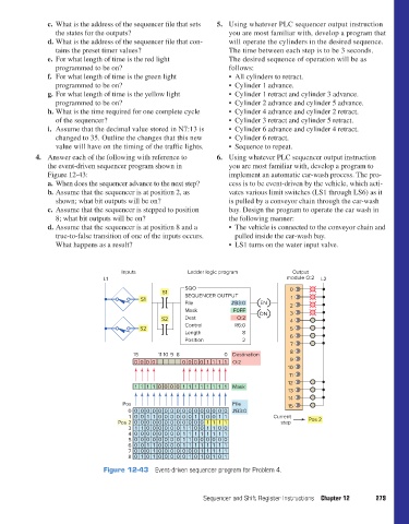
4. Answer each of the following with reference to 6. Using whatever PLC sequencer output instruction
the event-driven sequencer program shown in you are most familiar with, develop a program to
Figure 12-43: implement an automatic car-wash process. The pro-
a. When does the sequencer advance to the next step? cess is to be event-driven by the vehicle, which acti-
b. Assume that the sequencer is at position 2, as vates various limit switches (LS1 through LS6) as it
shown; what bit outputs will be on? is pulled by a conveyor chain through the car-wash
c. Assume that the sequencer is stepped to position bay. Design the program to operate the car wash in
8; what bit outputs will be on? the following manner:
d. Assume that the sequencer is at position 8 and a • The vehicle is connected to the conveyor chain and
true-to-false transition of one of the inputs occurs. pulled inside the car-wash bay.
What happens as a result? • LS1 turns on the water input valve.
Inputs Ladder logic program Output
L1 module O:2 L2
SQO 0
S1 SEQUENCER OUTPUT
S1 1
File #B3:0 EN 2
Mask F0FF DN 3
S2 Dest O:2 4
Control R6:0
S2 5
Length 8
Position 2 6
7
8
15 11 10 98 0 Destination
0 000 0000 11 11 O:2 9
10
11
12
0 1111 0 000 11111111 Mask
13
14
Pos File 15
0 0 0 0 0 0 0 0 0 0 0 0 0 0 0 0 0 #B3:0
1 0 0 1 1 0 0 0 0 0 0 1 1 0 0 1 1 Current Pos 2
Pos 2 0 0 0 0 0 0 0 0 0 0 0 0 1 1 1 1 step
3 1 1 0 0 0 0 0 0 1 1 0 0 1 1 0 0
4 0 0 0 0 0 0 0 0 1 1 1 1 1 1 1 1
5 0 0 0 0 0 0 0 0 1 1 0 0 0 0 0 0
6 0 0 1 1 0 0 0 0 1 1 1 1 1 1 1 1
7 0 0 0 1 0 0 0 0 0 0 0 1 1 1 1 1
8 0 1 0 1 0 0 0 0 0 1 0 1 0 1 0 1
Figure 12-43 Event-driven sequencer program for Problem 4.
Sequencer and Shift Register Instructions Chapter 12 279
pet73842_ch12_252-280.indd 279 03/11/15 7:20 PM