
Page 118 - Programmable Logic Controllers, Fifth Edition
P. 118
6.1 Electromagnetic Control Relays
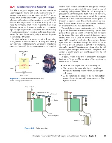
control relay. With no current flow through the coil (de-
energized), the armature is held away from the core of
The PLC’s original purpose was the replacement of the coil by spring tension. When the coil is energized, it
electromagnetic relays with a solid-state switching sys- produces an electromagnetic field. Action of this field,
tem that could be programmed. Although the PLC has re- in turn, causes the physical movement of the armature.
placed much of the relay control logic, electromagnetic Movement of the armature causes the contact points of
relays are still used as auxiliary devices to switch I/O field the relay to open or close. The coil and contacts are insu-
devices. The programmable controller is designed to re- lated from each other; therefore, under normal conditions,
place the physically small control relays that make logic no electric circuit will exist between them.
decisions but are not designed to handle heavy current or The symbol used to represent a control relay is shown in
high voltage (Figure 6-1). In addition, an understanding Figure 6-3. The contacts are represented by a pair of short
of electromagnetic relay operation and terminology is im- parallel lines and are identified with the coil by means
portant for correctly converting relay schematic diagrams of the letters. The letter M frequently indicates a motor
to ladder logic programs. starter, while CR is used for control relays. Normally
An electrical relay is a magnetic switch. It uses elec- open (NO) contacts are defined as those contacts that are
tromagnetism to switch contacts. A relay will usually open when no current flows through the coil but that close
have only one coil but may have any number of different as soon as the coil conducts a current or is energized.
contacts. Figure 6-2 illustrates the operation of a typical Normally closed (NC) contacts are closed when the coil
is de-energized and open when the coil is energized. Each
Output circuit contact is usually drawn as it would appear with the coil
de-energized.
A typical control relay used to control two pilot lights
Load
Contact is shown in Figure 6-4. The operation of the circuit can be
summarized as follows:
Relay
• With the switch open, coil CR is de-energized.
Coil
Switch • The circuit to the green pilot light is completed
– + through the normally closed contact, so this light
will be on.
Input circuit • At the same time, the circuit to the red pilot light is
Figure 6-1 Electromechanical control relay. opened through the normally open contact, so this
Source: Courtesy Tyco Electronics Ltd. light will be off.
Fixed contacts
Movable contact
Armature
Spring
Coil de-energized
+
Coil energized
–
Figure 6-2 Relay operation.
Developing Fundamental PLC Wiring Diagrams and Ladder Logic Programs Chapter 6 99
pet73842_ch06_098-130.indd 99 05/11/15 4:19 PM