Page 223 - Programmable Logic Controllers, Fifth Edition
P. 223

L1    Inputs              Ladder logic program          Outputs  L2
                                                      S1
                                                1                          MCR
                                            S1                                          PL1
                                                      S2                   PL1
                                           S2   2
                                                                                        PL2
                                           S3         S3                   PL2
                                                3                           L
                                           S4
                                                      S4                   PL2
                                                4                           U
                                           S5

                                           S6   5                          MCR
                                                      S5
                                                6                          MCR

                                                      S6    TON
                                                            TIMER ON DELAY
                                                7                               EN
                                                            Timer        T4:1
                                                            Time base     1:0   DN
                                                            Preset         10
                                                            Accumulated    0

                                                8                          MCR

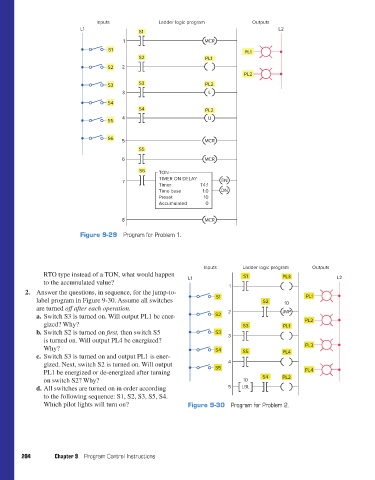
                                  Figure 9-29  Program for Problem 1.


                                                                           Inputs      Ladder logic program   Outputs
                       RTO type instead of a TON, what would happen                    S1           PL3               L2
                       to the accumulated value?                     L1
                                                                                   1
                 2. Answer the questions, in sequence, for the jump-to-
                    label program in Figure 9-30. Assume all switches          S1             S2     10     PL1
                    are turned off after each operation.
                    a. Switch S3 is turned on. Will output PL1 be ener-       S2   2                JMP
                       gized? Why?                                                     S3           PL1    PL2
                    b. Switch S2 is turned on first, then switch S5           S3
                       is turned on. Will output PL4 be energized?                 3
                       Why?                                                   S4       S5                   PL3
                    c. Switch S3 is turned on and output PL1 is ener-                               PL4
                       gized. Next, switch S2 is turned on. Will output            4
                       PL1 be energized or de-energized after turning         S5                            PL4
                       on switch S2? Why?                                              10     S4    PL2
                    d. All switches are turned on in order according               5   LBL
                       to the following sequence: S1, S2, S3, S5, S4.
                       Which pilot lights will turn on?              Figure 9-30  Program for Problem 2.


               204        Chapter 9  Program Control Instructions


          pet73842_ch09_184-206.indd   204                                                                              03/11/15   4:01 PM
   218   219   220   221   222   223   224   225   226   227   228