
Page 283 - Programmable Logic Controllers, Fifth Edition
P. 283
I:0/1
L1 Inputs Input Ladder logic program Output
module I:1 L2
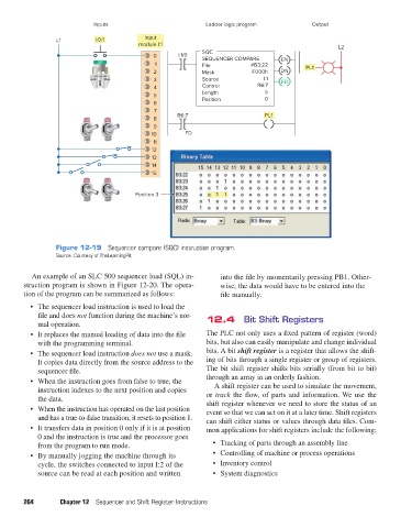
SQC
0 I:1/0
SEQUENCER COMPARE EN
1 File #B3:22 PL1
2 Mask F000h DN
3 Source I:1 FD
4 Control R6:7
5 Length 5
Position 0
6
7
R6:7 PL1
8
9
10 FD
11
12
13
14
15
Position 3
Figure 12-19 Sequencer compare (SQC) instruction program.
Source: Courtesy of TheLearningPit
An example of an SLC 500 sequencer load (SQL) in- into the file by momentarily pressing PB1. Other-
struction program is shown in Figure 12-20. The opera- wise, the data would have to be entered into the
tion of the program can be summarized as follows: file manually.
• The sequencer load instruction is used to load the
file and does not function during the machine’s nor- 12.4 Bit Shift Registers
mal operation.
• It replaces the manual loading of data into the file The PLC not only uses a fixed pattern of register (word)
with the programming terminal. bits, but also can easily manipulate and change individual
• The sequencer load instruction does not use a mask. bits. A bit shift register is a register that allows the shift-
It copies data directly from the source address to the ing of bits through a single register or group of registers.
sequencer file. The bit shift register shifts bits serially (from bit to bit)
• When the instruction goes from false to true, the through an array in an orderly fashion.
instruction indexes to the next position and copies A shift register can be used to simulate the movement,
the data. or track the flow, of parts and information. We use the
shift register whenever we need to store the status of an
• When the instruction has operated on the last position event so that we can act on it at a later time. Shift registers
and has a true-to-false transition, it resets to position 1. can shift either status or values through data files. Com-
• It transfers data in position 0 only if it is at position mon applications for shift registers include the following:
0 and the instruction is true and the processor goes
from the program to run mode. • Tracking of parts through an assembly line
• By manually jogging the machine through its • Controlling of machine or process operations
cycle, the switches connected to input I:2 of the • Inventory control
source can be read at each position and written • System diagnostics
264 Chapter 12 Sequencer and Shift Register Instructions
pet73842_ch12_252-280.indd 264 03/11/15 7:20 PM