
Page 346 - Programmable Logic Controllers, Fifth Edition
P. 346
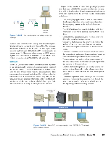
Figure 14-46 shows a smart belt packaging opera-
                                                                         tion that uses a SERCOS module interface in conjunc-
                                                                         tion with Allen-Bradley Kinetix 6000 multi-axis servo
                                                                         drive. The operation of the process can be summarized
                                                                         as follows:
                                        Connectors                         •  This packaging application is used to convert ran-
                                                                             domly spaced product into evenly spaced product
                                                                             that’s properly phased to the in-feed of another
                                                                             machine.
                               Field
                              device                                       •  The SERCOS interface module is linked with fiber
                                                       Fieldbus
                                                       interface             optic cable to the Allen-Bradley Kinetix 6000 servo
                                                                             drive.
                   Figure 14-44  Fieldbus implemented using daisy-chain
                   topology.                                               •  The randomly spaced product is fed by a conveyor
                                                                             driven by an induction-type motor.
                                                                           •  The servos that make up the smart belts follow the
                   standard that supports both analog and discrete signals.   in-feed of the next conveyor downstream so that
                   It is functionally comparable to DeviceNet. The physical   the smart belt’s speed is matched to that machine’s
                   media are  defined via  the RS-485 or fiber  optic trans-  speed.
                   mission technologies. PROFIBUS-DP communicates at       •  The input from the sensor on each smart belt senses
                   speeds up to 12 Mbps over distances up to 1200 meters.    the product and makes position corrections based on
                   Figure  14-45 illustrates a Siemens S7-200 Micro PLC      error calculations performed in the controller.
                   system connection to a PROFIBUS-DP network.
                                                                           •  The corrections are performed on a percentage of
                   SERCOS                                                    the total error, based on whether the belt is perform-
                   SERCOS (Serial Real-time Communications System)           ing a coarse or fine correction.
                   is an internationally approved communication standard   •  The first belts in the process are usually coarse cor-
                   for motion control. The SERCOS standard makes it pos-     rection belts and typically make a large correction
                   sible to use devices from various manufacturers.  This    for as much as 70 to 100% of the total phasing error
                   communication network is designed for high-speed serial   amount.
                   communication of standardized closed-loop data, in real   •  The last belts perform fine correcting for 100% of the
                   time, over a noise-immune fiber optic cable. The SERCOS   measured remaining phasing error even though the
                   interface modules use a single, digital fiber optic link,   total error is smaller, relative to what it was at
                   which eliminates as many as 18 digital wires per axis.    the beginning of the correcting process.


                                                            PROFIBUS-DP
                                                              module


                                                                         PROFIBUS-DP


                                             Figure 14-45  Micro PLC system connection to a PROFIBUS-DP network.
                                               Source: Courtesy Siemens.


                                                                Process Control, Network Systems, and SCADA  Chapter 14  327


          pet73842_ch14_305-332.indd   327                                                                              05/11/15   4:29 PM